How to set up line thickness for drawings in Creo 6.0? | Pen Tables
Drafting in Creo 6.0 is sometimes quite frustrating as it should not be since Creo is one the best CAD for engineers who work with large assemblies and also a wide variety of families of products with different sizes and varieties. Setting line thickness for drawings in creo is a myth for some people.
For people who are new to Creo, PTC Creo is a family or suite of CAD software, that supports product design for discrete manufacturers and is developed by PTC.
As I have mentioned during our Drafting work, we face many challenges. As I work through many features of Creo, One of my co-workers asked me how to change the line thickness for drawings in the latest Creo 6.0. Let us discuss How to set up line thickness for drawings in Creo 6.0.
Setting Line Thickness For Drawings in Creo 6.0
First of all, the setting will be the same as the older version with the current version of Creo 6.0
There will be two-aspect when you face this issue.
- While exporting a DWG/DXF file format to use in other CAD software such as AutoCAD
- While Exporting a PDF file to print on an A3 or A2 sheet (Pen Table Settings)
We will discuss these two areas deeply.
Setting Line Thickness for Exporting a DWG/DXF file
- Creo Parametric does not assign line width in drawing, especially for models displayed in views.
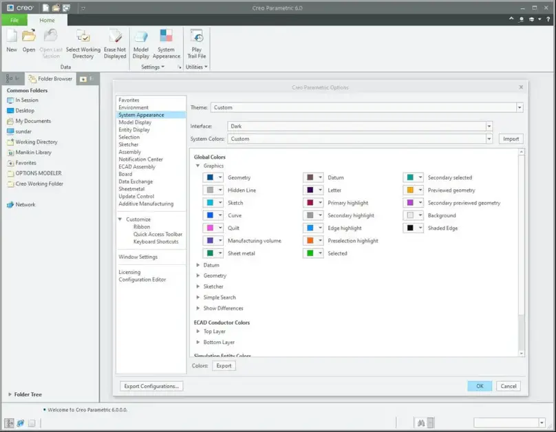
- Those lines are only assigned different system colours depending on their types (Geometry, Hidden Lines, Quilts, etc). They can be changed in the System Appearance section of the Options menu.
- Therefore the thickness is not transferred when exporting to DWG / DXF file formats unless explicitly setting a style and width on each item.
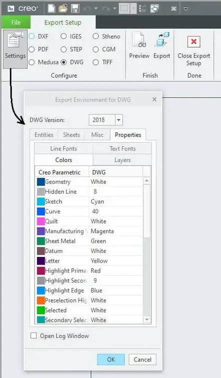
- However other information can be mapped during the export, like Colors, Layers or Fonts in the Export Setup > Settings > Properties dialogue for the latest Creo releases.
- The default values can be specified in a dxf_export.profile
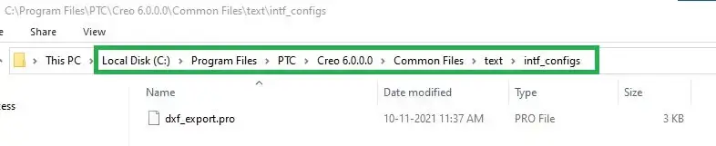
- An sample file will be available under <Creo Installation directory>\Common Files\text\intf_configs folder
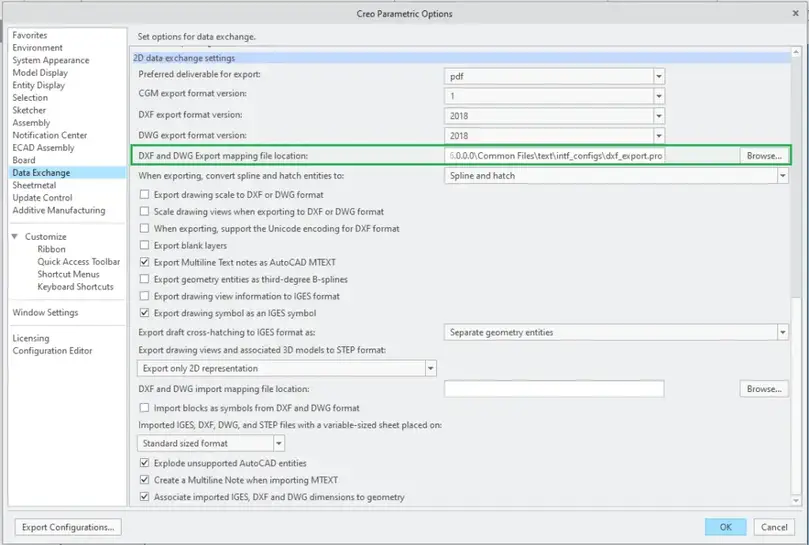
- The file location can be defined in the Data Exchange section of the Options menu and/or through the config.pro option intf2d_out_dxf_mapping_file
- Then, even if not allowed to directly show the thickness in the Graphic Area of the application itself, when the file is opened in Autocad the colours may be used to print with the proper line weight through Plot Style Tables:
- You can try troubleshooting techniques in the Autodesk article source to get the colours and line weight correctly imported.
- You could also explore ways to place the imported entities on Layers (for example selecting by colour) and define the line weight in their properties side the AutoCAD itself the other CAD software which they must provide.
- In Creo Parametric, as indicated above, an alternative could be:
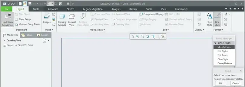
- Use the Layout > Line Style command and assign a line font and width to each drawing entity
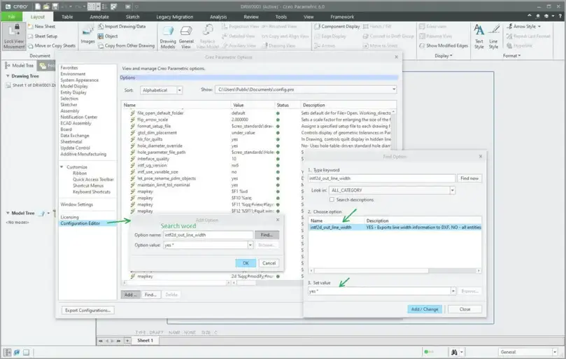
- Ensure the config.pro option intf2d_out_line_width is set to yes.
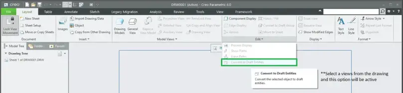
- Or convert the drawing view to draft entities to enable selection by rules to edit multiple items at once and manually modify the line thickness and colours.
PDF Export and Line Thickness:
When exporting to PDF, like plotting, it is possible to use a Pen Table and control the thickness for each system colour assigned to a pen.
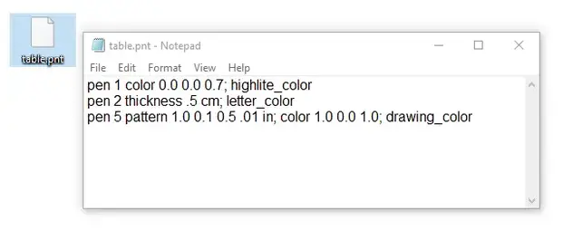
Pen table is nothing but a text file you create with attributes to override the system attributes. so this file can be created in the notepad in the windows operating system or any text editor of your choice.
- To Create a Pen Table File Open a text editor. (Save the file with the extension .pnt. For example, table.pnt or <filename>.pnt. The filename should be lowercase.)
- In order to change the existing pen table system attributes, assign your own line font, thickness, or colour to a pen using the table.pnt file. Any attribute that you specify overwrites the default instructions.
- The format for an entry in the table.pnt file is as follows:
pen # pattern values units; thickness value units; color values; <color_name>- Description of these attributes are as follows
- pattern—Specifies plotted line font definition drawn according to defined values in the given units. Values are created in the following order: first-line segment length, first space length, second-line segment length, second space length, and so on. For example: pen 3 pattern .1 .05 .025.05.
- thickness—Specifies plotted line thickness in the given units.
- colour—Specifies colour used for plotting; defines colour using proportions of red, green, and blue on a scale of 0 to 1. Works only on colour plotters.
- <color_name>—Corresponds to the default Creo Parametric colour that the system assigns to a particular entity type (to access the default system colours, click File > Options > System Colors, and then, in the System Colors tab, select Default from the Color scheme list.
- The following table lists the details of pen #
| Pen # | System Color | Mapping |
| 1 | GeometryCurveManufacturing volumeQuiltPreselection highlightPreview geometrySecondary preview geometry | Visible geometry (plot as solid lines, except where noted): Cross-section cutting plane lines: plot as phantom lines cross-section cutting plane arrows and text drawing format and boundary tag next centerline line font with white color |
| 2 | Letter Datum | All items plot as solid lines (except where noted): Dimension linesLeadersAxes and centerlines: plot as centerlinesGeometric tolerance linesAll text (except cross-section text)Balloon notes cross-hatchingCenterline line font with a yellow colour brown portion of datum planes |
| 3 | Hidden Line | Hidden lines: plot as dashed lines, phantom font |
| 4 | Primary highlightSelectedSecondary selected | All items plot as solid lines: Spline surface grid (does not plot in drawings) |
| 5 | Sheet metal | Sheet metal colour entities |
| 6 | Sketched Curve | Sketcher section entities |
| 7 | Secondary highlight | Toggled sections, greyed dimensions and text, dimmed tangent edgesDark grey portion of datum planes |
| 8 | Edge highlight | Spline surface grid |
- by default, Creo Parametric uses a pen table file table.pnt in the working directory. If table.pnt is not found in the working directory, then Creo Parametric looks for the file in <creo_loadpoint>/common_files/<datecode>/text/table.pnt.
General Guidelines to keep in mind while writing pen tables for Creo
- More than 8 pens can be supported.
- All units must be set in inches (IN) or centimetres (CM). Using millimetres (MM) results in a syntax error.
- It is possible to assign more than one colour to the same pen in the table.pnt file.
- Separate multiple colour names by spaces or commas.
- Separate attributes by semicolons.
- Include any or all attributes for each pen.
- Attributes that were not included in the table.pnt file appears unchanged, as in normal plotting.
- Use units in inches (in) or centimetres (cm), and mix them in font definitions; for example, you can specify a font pattern in inches and thickness in centimetres.
- Use the backslash (\) at the end of a line to continue the entry on the next line.
- Use an exclamation point (!) at the beginning of a line in the file to make it a comment.
Example Pen Table
Let us know if this helps you set the line thickness of the drawing you are working…
没有评论:
发表评论