![]()
The Problem: Exporting yellow text and dimensions in DXF.
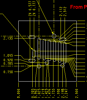
Anyone who has to deal with outside machine shops or vendors, has had to export a drawing in a format other CAD systems can read. A common export format is DXF, which stands for Drawing Exchange Format. If you have done this from Pro/E, you know many shops complain about dimensions, text, and other draft entities being yellow. This creates problems when the file is imported in another CAD or CAM system that has a white or light background. There is not enough contrast to see the yellow as shown in the figure below.
 |  | |
 |  | |
 |
Printing the drawing does not usually solve the problem because the printed output can have yellow or very light grayscale on white paper. Many CAD programs (or operators) do not have the ability to change the background color to black and make the yellow readable -- then if they do, the printing problem may remain. If all the entities on a drawing are white, the CAD system will usually show them as black on the white background and on the printed page.
The Solution: Make Pro/E assign the desired color(s) as it creates the DXF.
Changing colors of the entities in the drawing in Pro/E before creating the DXF file will not solve the problem, it actually creates some new problems that will be discussed later. Release 2000i (and above) provides the ability to map alternate colors to DXF files using a new configuration file called "dxf_export.pro". This file must exist in the current working directory to be read. A template dxf_export.pro file is provided in the "loadpoint"/text/intf_configs directory. The line of interest for changing yellow dimensions and text is LETTER_COLOR. By changing this line to read "map_color LETTER_COLOR 5" (case is important) the yellow draft entities will import into AutoCAD (and other programs) as blue. (The number 5 corresponds to the AutoCAD color pallet.) A few common AutoCAD colors are:
- 3 = RED
- 5 = BLUE
- 7 = WHITE
For best results, try 7. This will make all draft entities show up on any background color, just like geometry.
|
The Bugs: - as usual - in the solution.
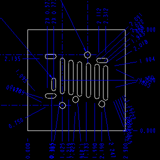
There are two bugs associated with DXF output -- and they are not trivial. In order for the dxf_export.pro file to work with dimensions, the "copy_dxf_dimmed_pict" line in the config.pro file must be set to "no". Once this is set to "no" the colors will change but the dimension formatting will be lost. This can render the drawing unreadable if there are many created or ordinate dimensions having leader jogs.
Figure 2 is a great example of a loss of formatting.
The other bug is if the color of the entities have ever been changed, they will not be converted as specified in the dxf_export.pro file. This is particularly troublesome because that is usually the first thing tried when struggling to convert the yellow entities to some other color ... wouldn't you know!
|
The Workaround:
If you need to change the colors and preserve dimension formatting, then the drawing must be converted the hard way.
- Export to a DXF file as usual.
- Create a new drawing that is empty; has no default model.
- Import the DXF file you just created using APPEND.
- Use: DETAIL > MODIFY > MODIFY TEXT > MODIFY TEXT STYLE to change the color of the text. (The Modify Text Style menu is shown as Figure 3.) Also, use the "PICK MANY" option to help selection go faster.
- Use: DETAIL > MODIFY > MODIFY LINE STYLE > PICK MANY to change the color of the lines.
- Export the new drawing as a DXF and this newest DXF will have the colors you have chosen.
This works best if all the colors are changed to White. Otherwise, it is difficult to get the dimension text to match the color of the leaders.
|


没有评论:
发表评论