M1194W01
1TO8
We have over 300 coatings in our portfolio, of which many were created to provide wear resistance. Wear resistant coatings solve industries challenges related to abrasion, erosion, galling and fretting. Most of these components were designed using carbon steel, stainless steel, tool steel or aluminum which may have been protected by anodizing, nitriding, carburizing or plating with hard chrome. We can improve the life of these components and the quality impact on your products by utilizing carbide, ceramic, cermet or metallic thermal spray coatings or by laser cladding / hardfacing.
Carbide
Carbide coatings are used to protect a part against abrasion, erosion, galling, and fretting. Most coatings are applied by high velocity thermal spray processes but plasma can be used. They improve the surface features of the part to improve hardness, retain surface characteristics, provide durability and toughness and resist metal to metal adhesion. There are numerous types of carbide coatings which fall into these main families:
Ceramic
Ceramic coatings also called oxide coatings are used to protect a part against abrasion, sliding wear, fretting and galling. Ceramic coatings also offer corrosion resistance when paired with sealers, so they can be selected to provide wear resistance when in contact with corrosive fluids. Ceramic coatings are applied by plasma spray and detonation gun processes. Listed below are the common types of ceramic coatings.
Cermet
Cermet coatings are designed to function like carbide and ceramic coatings but at higher temperatures, up to ~1100°C (~2000°F). The binder is modified by using superalloys or MCrAlY powders, where “M” can be nickel, cobalt or a combination of both. The modified binder is able to survive oxidation at the higher temperatures. Listed below are some example compositions.
Metal Alloy
Metal alloy coatings have a base alloy that is corrosion resistant plus some hard phases for wear resistance. Various methods of thermal spraying can be used to apply the metal alloy coating. Some common chemistries are listed:
Laser Cladding / Hardfacing
Laser cladding’s metallurgical bond, consistent chemistry and ductility combat wear and corrosion in areas where thermal spray coatings and chrome plating fall short due to brittleness, permeable morphology and mechanical bond. Numerous materials and blends are available with some popular chemistries listed below:

Posted on : March 11, 2022 By GREFEE
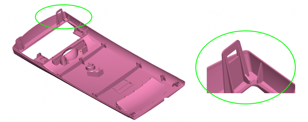
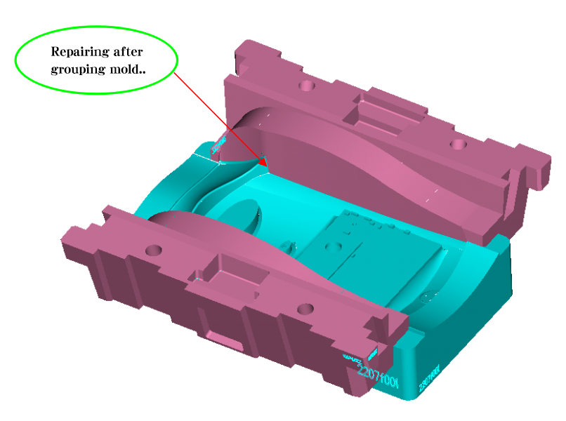
Undercuts treatment
Movement principles & design elements of diagonal bracing pin block
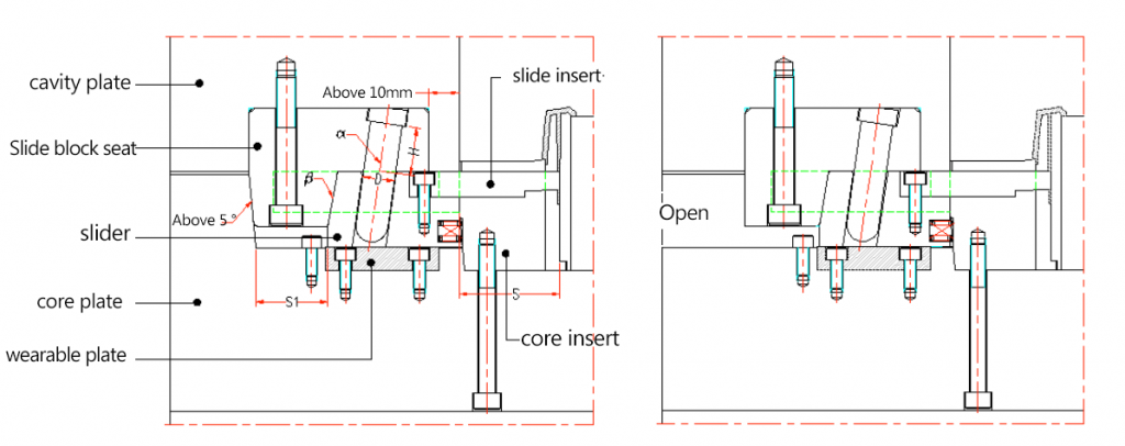
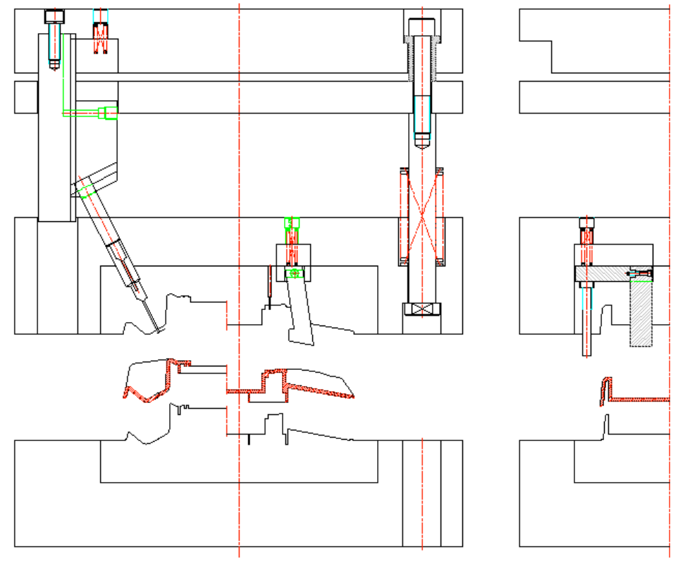
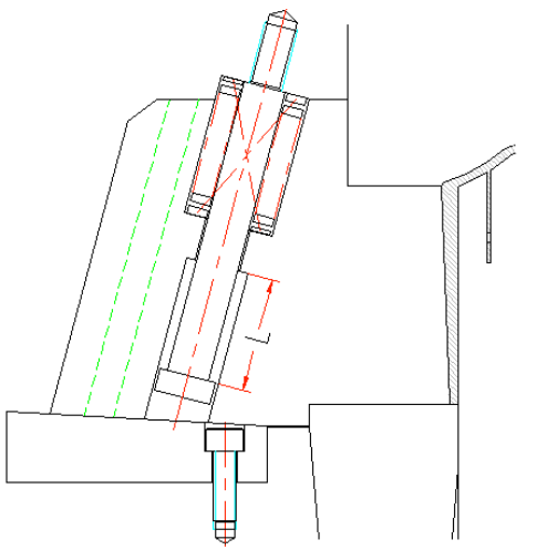
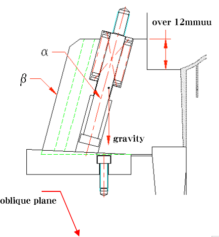
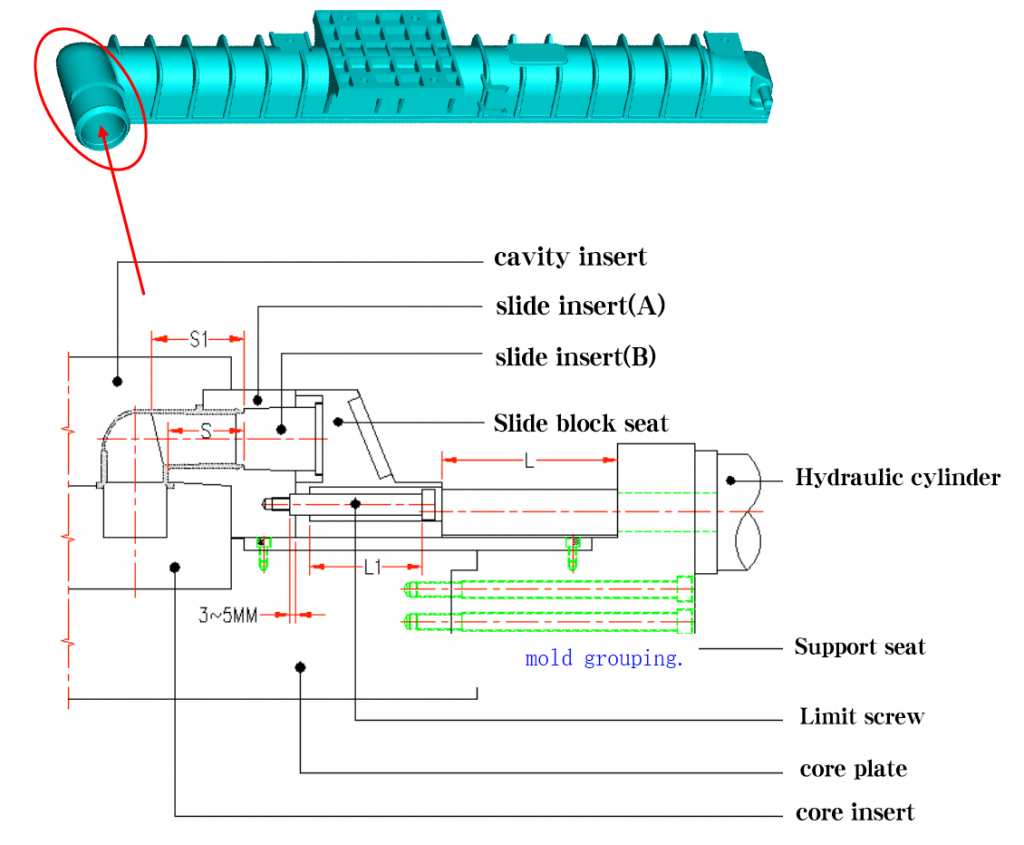
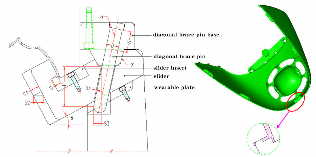
Undercuts treatment uses the mold opening movement and ejection force to causes the tendency of relatively motion between angle pin and slider. There are two movements to make it separate from the undercut : mold opening direction & horizontal direction. As the below pic shows:

in the pic:
β=α+2°~3°(avoid any parts contacts or blocks when group molding & reduce friction when opening molds)
α≦25°(α is the obliquity of taper pin)
L=1.5D (L is matching length)
S=T+2~3mm(S, the distance of horizontal movement of slider, T, the end product undercut
S=(L1xsina-δ)/cosα(δ – the space between taper pin and slider, normally is 0.5MM,L1is the taper pin vertical distance inside the slider)
Clamping methods & applicable situations of diagonal bracing tip
| Diagram | Description |
 | Suits for situations, like thin mold and the top clamping plate and cavity plate are closed. The contact area is long and stable. |
 | Suits for situations, like thick mold, large mold cavity. applicable to two plate mold/three plate mold.The contact area L≧1.5D(D is diameter of diagonal bracing tip), good stability |
 | Suits for thick mold applicable to two plate mold/three plate mold contact area L≧1.5D(D is diameter of angle pin), poor stability, hard to processing |
 | Suits for situations, like thin mold and the top plate mold and cavity plate can be separated. Long contact area, good stability |
Movement principles & design elements of pulling block
The mold opening movement of molding machine causes a tendency of relatively motion between pulling blocks and sliders.
See pic below:
in the pic above:
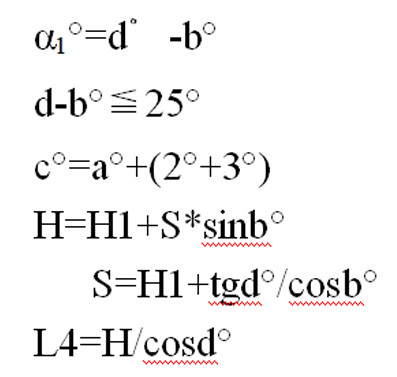
β=α≦25° (α – the obliquity of pulling block)
H1≧1.5W (H1-matching distance)
S=T+2~3mm (S-distance of horizontal movement of slider, T- end product undercut)
S=H*sinα-δ/cosα(δ – the space between diagonal bracing tip and sliders, normally is 0.5MM,L1is the vertical distance of
H-vertical distance of pulling block inside the slider)
C- motion stopping surface so the pulling block form doesn’t need motion-stoping surface(no space)
Slider locking & fixing solutions
There is a huge pressure during the molding machine injection process. To avoid affecting the side and appearance(eg. burrs) of end products, we should keep the slider and core unmoved when molding machine injection. So the slider should use locking fixed method to keep it stay. normally, this part is motion-stoping block or heel.
Some common locking methods:
| Diagram | Description | Diagram | Description |
 | The sliders are pieced together, normally used for standard products. Normally used standard products, check standard parts catalogue. Good structure and hardness. Applicable to situations needing strong locking force. | 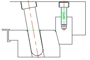 | Use insert mode to lock. Applicable to wide sliders. |
 | Use integrated locking mode. Good rigidity and structure. Hard to processing. Short Demolding distance. Applicable to small molds | 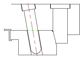 | Use insert mode Applicable to wide sliders |
 | Pulling or stopping Poor stability Applicable to situations of small slider space | 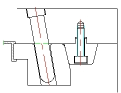 | Are pieced together Good rigidity Applicable to situations of large space |
Fixed methods of slider
The slider will move a certain distance in mold opening. One way to make the slider return back smoothly is to use equipment to fix it and it should be flexible and stable so that the slider will stay at where it should be. Some exceptional situations do not need fixed equipments, like left to right slider, so it is suggested to apply a fixed equipment.
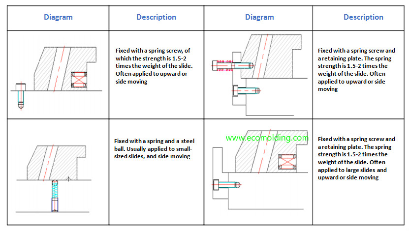
| Equipment for fixing: diagram | Description |
 | Fixing slider with spring screw, the strength of spring is 1.5-2 times the weight of slider. Applicable to upward or lateral core pulling. |
 | Fixed by spring steel ball. Normally for small sliders for lateral core pulling. |
 | Fixed by spring screw and guard. Strength of spring is 1.5-2 times the weight of slider. Applicable to upward and lateral core pulling. |
 | Fixed by spring guard, Strength of spring is 1.5-2 times the weight of slider. Applicable to big slider, upward and lateral core pulling. |
Connecting method of slide insert
How slider head insert connected is controlled by end product. Different end products have different connecting methods.
The slider head insert connected methods details:
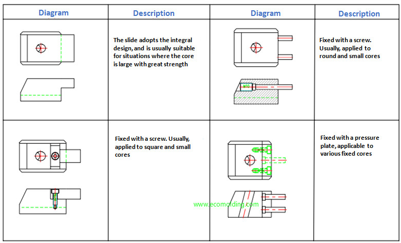
| Diagram | Description | Diagram | Description |
 | Integrated structure Applicable to situations of large cores, good strength. | 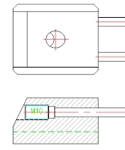 | Fixed by screw. Applicable to situations of cores, round, or cores are small. |
 | Fixed by screw. Applicable to situations of square cores/small or medium cores | 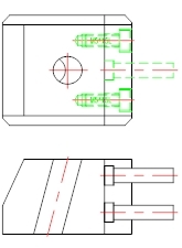 | Fixed by screw. Applicable to situations of square cores/small or medium cores |
Guide form of sliding block
In the slide guiding, the slider must be smooth and stable so that no stutters or beats, which will affect the aspects, like quality and service life of mold. (Link for the specifications of platen)
The common sliding guide forms are shown in the figure below.
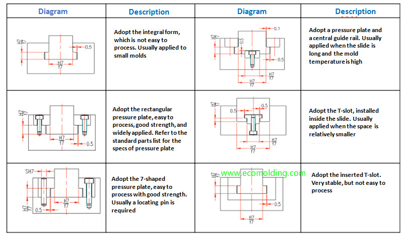
| Diagram | Description | Diagram | Description |
 | Integrated manufacturing mode, hard to manufacture, applicable to small mold manufacturing. | 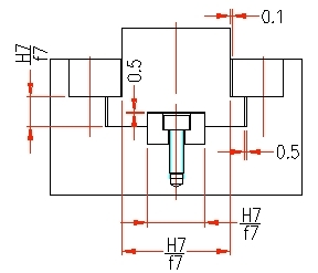 | Clamping plate ¢ral rail mode. Applicable to situations of long slider and high cavity temperate. |
 | Rectangle platen. Easy to manufacture. Fine strength, wide range of application, the specifications of platen is on standard parts list. | 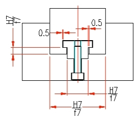 | “T” groove inside the slider. Applicable to situations of small space, like slide inside the slider. |
 | Applied “7” shaped clamping plate. Easy to manufacture, good strength. normally fixing with pinhole together. | 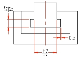 | Inserted “T” groove, good stability, hard to manufacture. |
Calculation of tilt slider index
Due to the undercut surface of the end product is tilt, so the move direction of slider should follow the direction of end products’ undercut surface, otherwise it will cause damages when pulling the end product.
When the angle situation between the slider core pulling and the parting surface is called the slider pulling direction moving-die.
Shown as pic:

Situation when the angle between slide core pulling direction and parting surface is slider pulling direction fixed-die.
Shown as below:
master mold runner slider
application features:
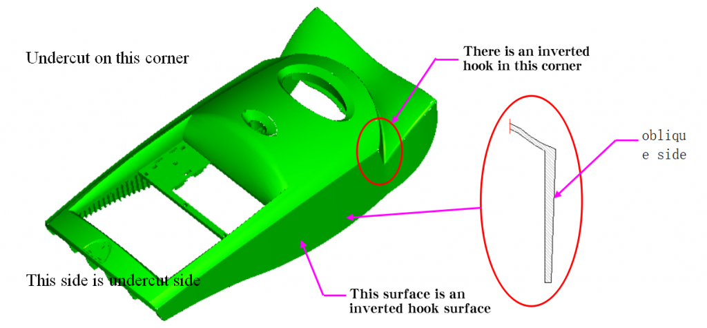
Undercuts forming on the side of master mold
Marks are allowed on the appearance
Medium slider forming area
Shown as below:
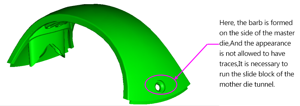
Undercut forming on the side of master mold. No marks allowed on appearance. Need to switch to master mold runner slider.
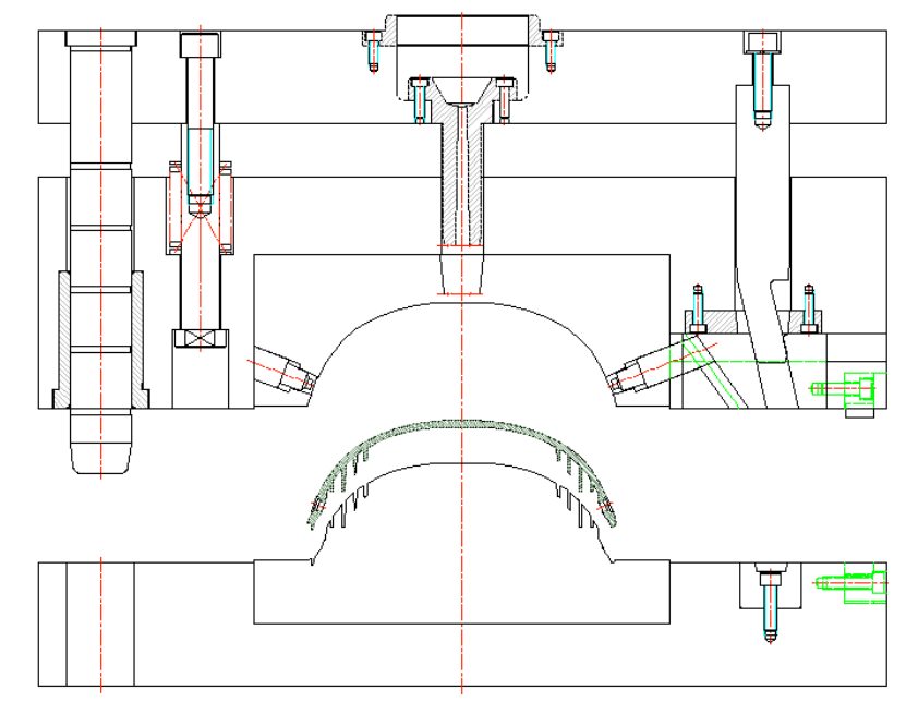
Master mold tunnel block shown as below:

gst mold opening:
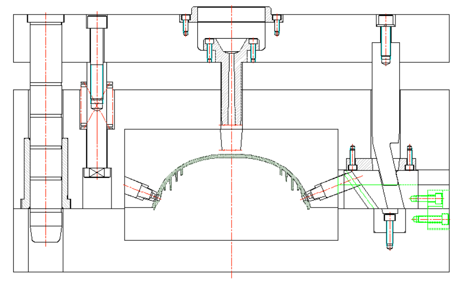
second mold opening:
second mold Designing tips
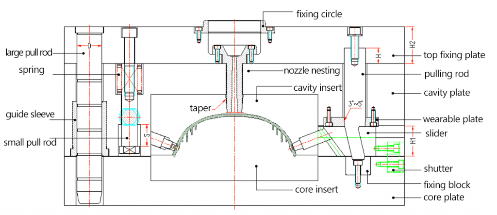
a. Thickness of top clamping plate H2≧1.5D (D – diameter of large tie rod; hyperlink of large tie rod diameter calculation, three play mold large tie rod calculation; H2- thickness of top clamping plate).
b. Depth of pulling block inserted on the top clamping plate H≧2/3H2
c. There should has taper on SPRUE BUSHING head to fit for clamping and should be on the top clamping plate to avoid brush nozzle on the molding machine separating from SPRUE BUSHING and then result in brush, which is inconvenient to take out and affects next injection.
d.when pulling block inside the cavity plate, should reduce material.
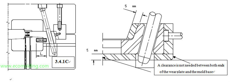
e.The wearable plate should be 0.5mm higher than master mold plate to protect the taste mold plate and support the support pulling block to prevent it from distorting due to the external force.
f. Small pull rod limit stroke: S≦2/3H1 assist with mold clamping. (H1 – height of the slider)
g. It is best to have fixed block on the front of pole, easy to adjust and processing, consist three point bearing, increase the strength of pulling block.
h.To make the wearable block assemble smoothly, E point should on the right of D point. Shown as below:

I. When assembling slide base and pulling block, need to notice about the relationship between size B and B1, it shoulbe B>B1, while in order to assemble smoothly, can also dig through the rear mold located after the slide base.
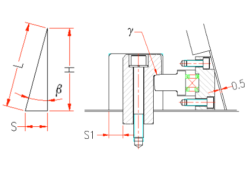
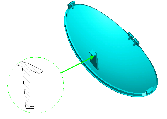
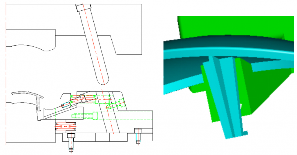
Dos and don’ts & calculation formula of double “T” groove
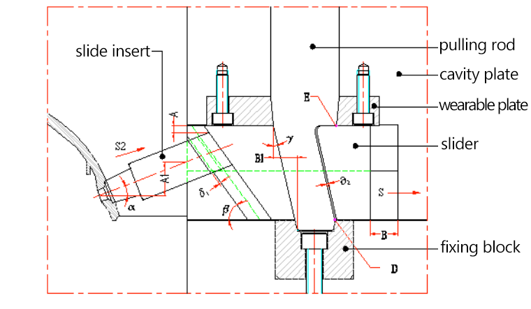
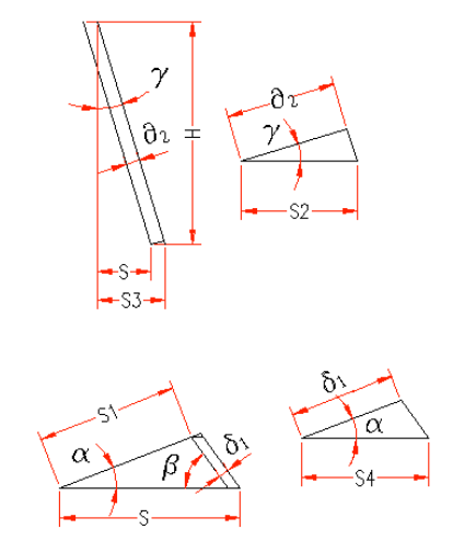
Shown as above:
S3=H*tgγ;
(H – the decreased height of slide block which is the small pull rod stroke; γ – the angle of pulling block)
S2=δ2*cosγ;
(δ2 – the space between pulling block and slide block, normally is 0.5mm)
S=S3-S2=H*tgγ-δ2*cosγ=(H*sinγ-δ2)/cosγ;
(S — horizontal moving distance of slide block)
S4=δ1/cosα;
(δ1 – slider insert and space between sliders;α -tilt angle of slider insert)
S1=(H*sinβ-δ1)/sin(α+β);
(β – space between grooves,normally is 0.5mm;S1- distance of slider insert out from the undercut)
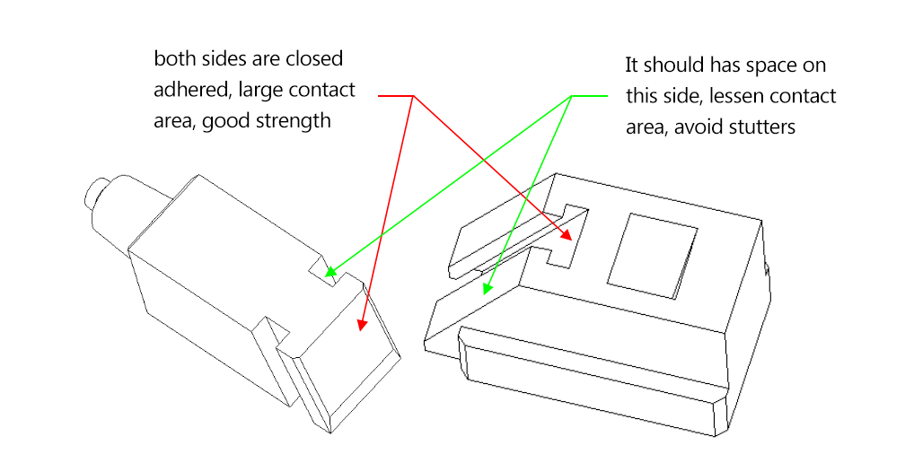
Dos and donts:
a. Assemble requirements: assemble the slider insert and inclined insert hole, it should notice the relationship between the size A and A1, should be A>A1.
b. Double “T” groove tolerance, shown as below:
Case of Assemble matters
Die sketch
pic above :
Slide insert can be put inside the core insert without problems, required S1>S or open the core plate.
β=α+2°~3° (easy to open mold and reduce scratches)
H≧1.5D H is diagonal brace pin matching length; D is diameter of diagonal brace pin)
Double “T” groove structure model:
Double “T” groove structure model:

Cavity explosive slider
applicable situations of explosive slide block
Generally, forming on the cavity side and large slider forming area, especially using slider when the cavity side is very deep.
Explosive slider as blow pic shows:
mold opening state:
Stroke calculation:
Shown in the pic below:
S=L*sinβ (β- “T” groove angle;L stroke along the “T” groove direction; S – distance of slide block horizontal movement)
H=L*cosβ (H distance of slide block vertical distance)
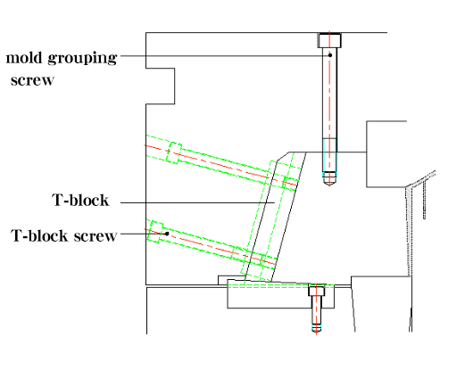
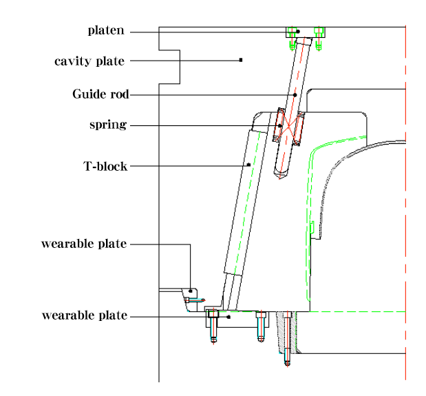
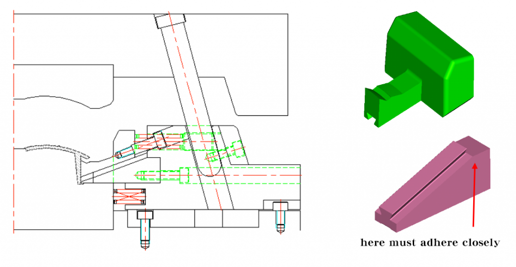
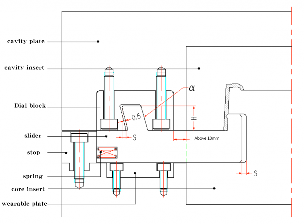
Design tips and notices of explosive slide block
Shown as the pic on the right:
a.bottom wearable plate needs bevel, reduce loss between slide block and core plate, normally takes 1.5˚~3˚, assemble location be at the 3 / 4 of the center of gravity of the slide block.
b.S1>S (S – distance of slide block horizontal movement)
c. the wearable plate on the back of slide block and should be 0.5 mm higher than slide block’s back.
e. The angle between block and grab hook γ> the wearable plate obliquity.
f.β=α (β is “T” groove angle;α is lmit rod angle)
g. T – block should be longer and 10 mm higher than cavity plate.
h. Slide block head should have die screw, easy to group the mold. Need to take down when testing mold
i. Lock T-block screw should be vertical to T block.
j. The spring at the head, should calculate the weight of slide block.
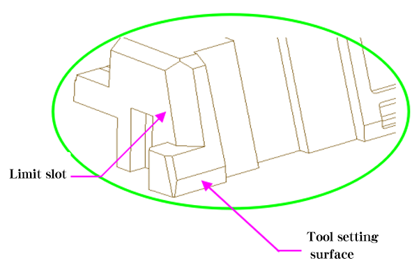
k. The back of the slide block should be tool setting plane.
l. Both flanks of slide block should have limit groove.
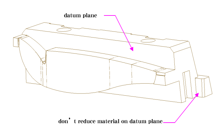
m. The slide block head must have datum plane to provide convenience for grouping mold. The processing base level is normally over 8mm.
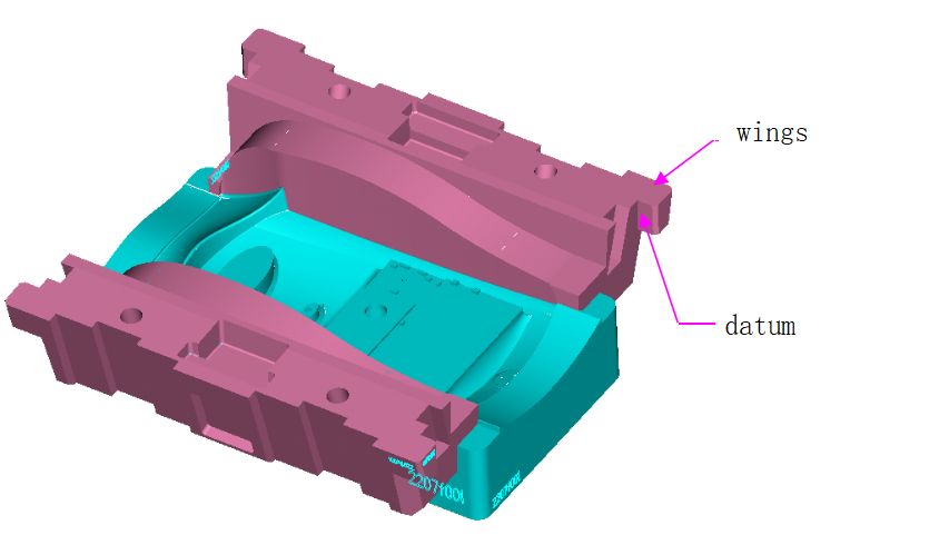
n. Explosive slide block must have shoulder (wings for fixing) to provide convenience for grouping mold and also a base level is necessary, cannot reduce the material)
The assemble location depends on the location of the gravity of slide block.
Dos and don’ts of Extra deep explosive slide block
the guide rod should assemble from the cavity plate
a、Cavity plate should be embedded into the core plate,avoid the cavity plate outward lift, enhance the mold strength
b.wearable plates needed at the protruding side of cavity plate, avoid scratches, easy to adjust.
c. Other precautions are the same as above
Place ejector pin inside slider
Generally, for thick and deep products’ wall, the side of the wall has many core pulling holes. The core pulling force is strong, so when moving the slide block, the product might be distorted or scratched. To avoid these happening, we need to place the ejector pin inside the slide block to stop the distortion or scratches.
A. Place ejector pin inside slide block (example 1)
B. Two common ways to place the ejector pin inside slide block, shown as below:
Delay slider
1. The outside product pulling force is strong, avoid distortion.
2. Use delay slider to operate forced demolding.
The pic below is water pipe and water pipe delay diagram:
1st mold
Finishing state after 2nd mold opening
oblique slider
1. Application range of oblique slider Normally applied in the products with slider structure, at the same time, along the slider’s direction, the end product also has undercut, which indicates that we can apply oblique slider.
note:
Pic on the right is typical case of oblique slider
2. Oblique slider diagram:

3.internal slider
(1) use boss form (seen as below)
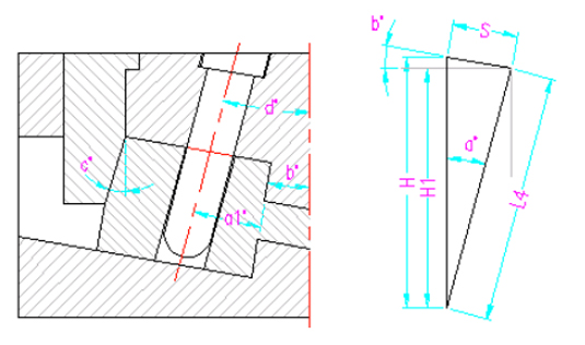
Use the form of diagonal brace pin (as shown below)
S1 = S + 1mm above(S, undercut distance;S1 distance of slider moving
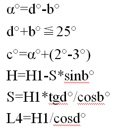
S2=S1/cosβ (S2, horizontal distance of slider;β obliquity of slider)
S2=S3=(H1*sinα-0.5)/cosα (H1, relative vertical height; obliquity of diagonal brace pin ≦25)°
γ=α+2°~3°
H≧1.5D (D, diameter of diagonal brace pin; H, matching distance of diagonal brace pin)
*Detailed dimension calculation hyperlink oblique slider calculation*
Calculation of core pulling force & strength checking
1. Calculation of core pulling force
After cooling, the plastic will be narrowing and shortening, including the die core and the other parts (like oblique tip, slider, insert etc)Therefore, we must consider the enclosed strength that end product impact on slider, stress state, see pic on the right
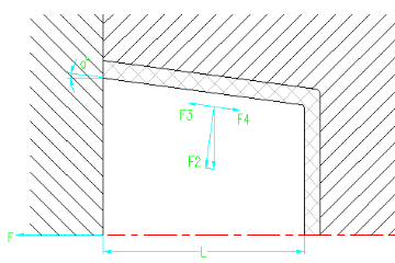
note:
F=F4*cosα-F3cosα=(F4-F3)*cosα
F—core pulling force(N);
F3—F2 lateral component(N)
F4— core pulling resistance(N);
α—obliquity of de-molding. as α is normally low, so cosα=1
That is F=F4-F3
But F2=F1-cosα
F3=F2tgα=F1cosα*tgα=F1*sinα
F4=F2*μ=μ-F1cosα
So F=F4-F3=μ*F1cosα-F1sinα=F1(μcosα-sinα)
F1——the enclosed strength that plastic on core (N)
F2—perpendicular to positive pressure on the surface of core(N)
μ—the friction coefficient between palstic and steel, normally is around 0.2
While F1=CLF.
The average circumference of core cross-section part which enclosed by plastic.
L—the distance of core part enclosed by plastic (CM)
F0—enclosed strength of unit area, normally 7.85~11.77MPA
Namely F=100CLF0(μcosα-sinα) (N)
2. Diagonal bracing tip diameter checking:
The diameter of diagonal bracing tip is affected by many factors, like obliquity, length, and required de-molding distance. Thus, in designing, some parameters should be adjusted and matched to obtain the best result to make sure the slider to move smoothly. Calculation formula:
Note:P – maximum bending force on taper pin
L— bending moment
P1—core pulling resistance
H— distance from core pulling hole center to point A
α°—obliquity of taper pin
P2—mold opening force
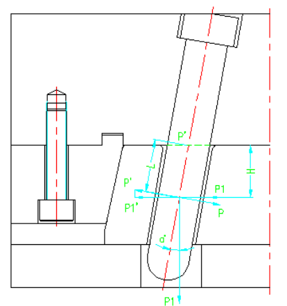
From the pic we know:
P=P1/cosα (KN)
M curve=PL (KN)
Which is M curve≦[σcurve]*W (KN)
namely PL=[σ curve]*W (KN)
W—bending section coefficient
[σ curve]—permissible bending stress(for carbon steel – 13.7KN/CM2 (137MPA)
M curve—maximum moment on taper pin
Namely: W=(πd4/64)/(D/2)= πd3/32=0.1d3
0.1d3=pL/[σ]=PH/([σ]cosα)
0.1d3=pL/[σ]curve=PH/([σ]curve cosα)
D=3√(ph/0.1[σ]cosα (cm)
D=3√(ph/0.1[σ] curve cosα (cm)
3.size of pulling block section checking
The size of pulling block section checking is as same as the calculation of diagonal bracing tip. It only needs to alter the last step. Formula:
W=bh2/b
When b=2/3h, W=h3/9
h3/9=pL/[σ] curve =PH/([σ] curve cosα)
H=3√9PH/([σ] curve cosα) (cm)
When b=h, W=H3/b]
H=3√(6ph/[σ] curve*cosα) (cm)
h—long side of puling block section(cm)
b—short side of pulling block section(cm)


===========================================
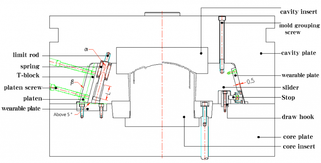
Basic Principles of the Slider
Due to the special requirements of a product, the mold release direction of a particular part may not be consistent with the mold opening direction of the injection molding machine (product undercut), the slider,also known as slide,is a mold mechanism that is developed to solve the issues with the undercut. The basic principle is to turn the vertical movement of mold opening / closing into a horizontal motion. In order to cope with the situation that the undercut is located in the core or cavity, different structural forms are developed:
Note:
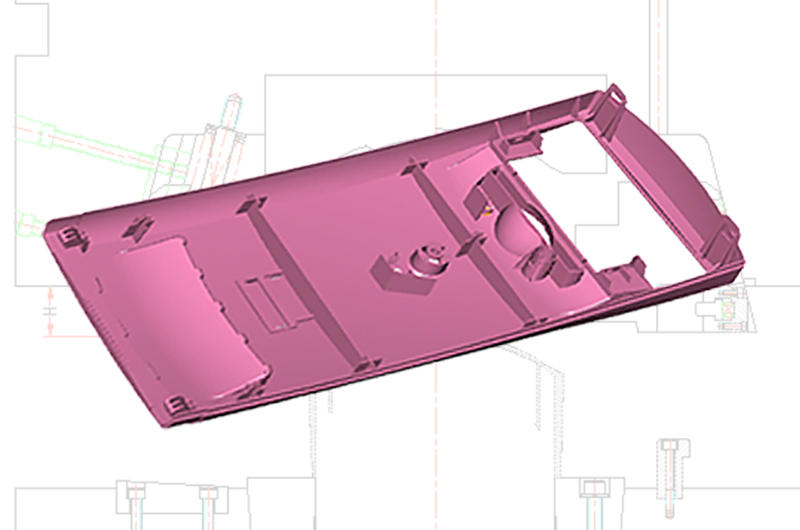
To mold a product with a deep cavity, of which the side wall does not allow a draft angle, but requires a high gloss, the mold structure also needs to adopt slider mechanism.
Structural Composition of the Slide
The slide mechanism is usually comprised of the following basic components.
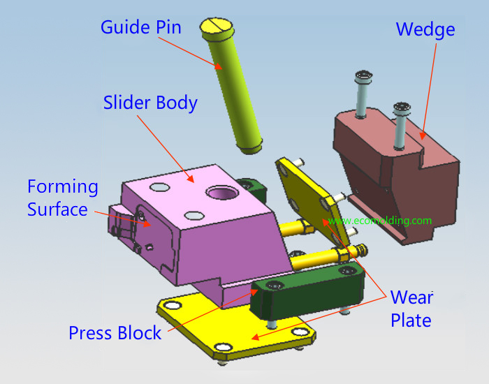
Note:
During slide operation, since the slide, the press plate, the wedge, the guide pin and the wear plate are subject to long-period wear, surface nitriding must be performed to minimize surface wear.
Design of the Angle Pin(Guide pin)
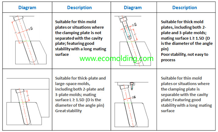
1: How the angle pin locks and where it is used
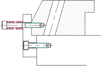
2: How the Guide Block Moves and Its Design Points
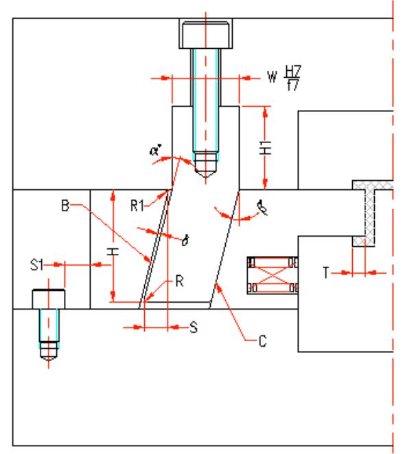
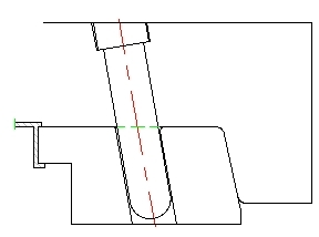
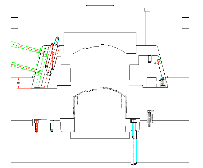
The mold opening action of the injection molding machine is leveraged to make the guide block and the slide move relatively, and surface B engages with the slide to make it move in two directions – the mold opening direction and the horizontal direction, so that it disengages with the undercut. The guide block acts as an angle pin when the mold opens, and as a locking block during mold closing.
See the figure as below:
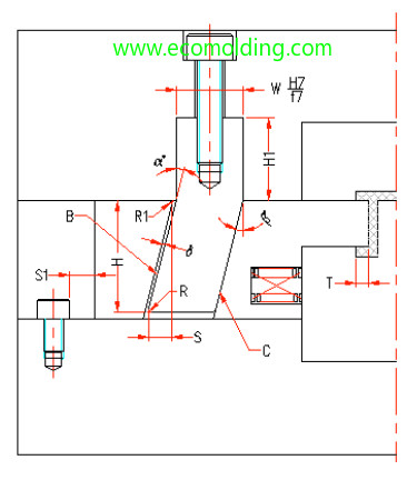
β = α ≦ 25° (α is the tilt angle of the guide block);
H1 ≧ 1.5W (H1 is the corresponding length);
S = T + 2-3mm (S is the horizontal travel distance of the slide; T is the undercut of the finished product);
S = H * sinα-δ / cosα(δ is the gap between the angle pin and the slide, generally is 0.5MM;
H is the vertical distance of the guide block in the slide);
C is the stop surface, so generally a stop block is not needed when the guide block is used (gaps not allowed).
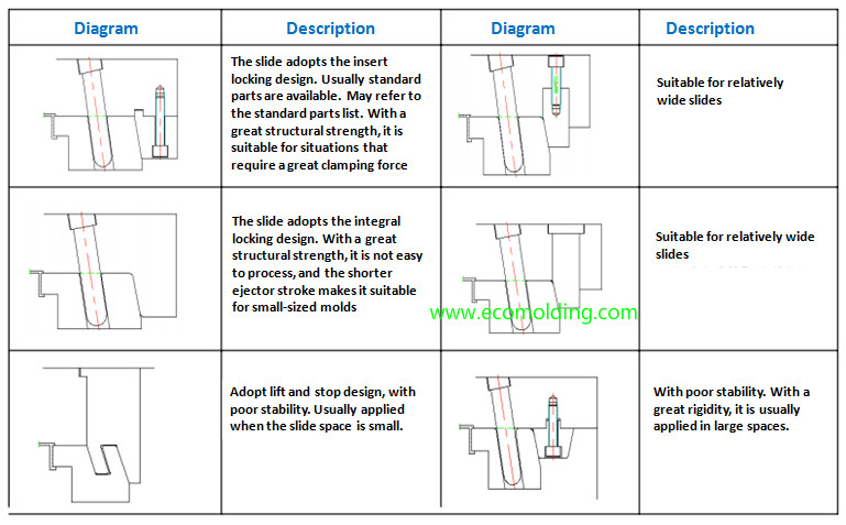
How the Slider Locks
Since great pressure is generated during the plastic injection molding process of a product, to prevent the slider from being displaced by the pressure, which may affect the dimensions and appearance of the finished product (such as flashing), the slider should be locked.
Commonly seen locking methods are shown below:
How the Slider Is Located
The slide travels a certain distance during mold opening. Therefore, to guarantee safe slider return, the slider must be equipped with a locking device, which needs to be flexible and reliable to ensure that the slide stays where it is. However, in some special cases, a locking device is not necessary, such as the slider that moves from left to right. But to ensure safety, it is better to have a locking device installed.
How to Connect the Slider Insert
The connection method for the slider insert is determined by the finished product, since it may vary with different products. The specific connection methods are shown as follows:
Sliding Guide of the Slide
Sliding guide(sliding rail) has to ensure that the slider moves smoothly and stably, so the slide does not get stuck or bounce during the plastic injection molding process, or product and mold service life will be affected. Sliding guide has to ensure that the slider moves smoothly and stably, so the slider does not get stuck or bounce during the plastic injection molding process, or product and mold service life will be affected.
The commonly used sliding guides are shown below:
=======================================
1. When designing the injection mold sliders, the biggest clearance between the slider and the product should be at least 2 – 3mm.


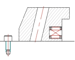
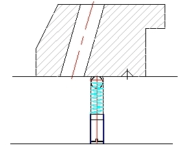
For upward (including inclined ones) sliders, there are raised fine inserts and pins. When there’s an ejector pin under the slider, a spring can be applied to facilitate return.


If the height of the guide pin is larger than 100mm (see Fig. 3.7.1A) and the cavity slider needs to be lifted before A and B plates separate from each other, a Air/Hydraulic cylinder may be applied to drive it (see Fig. 3.7.2B).


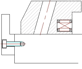
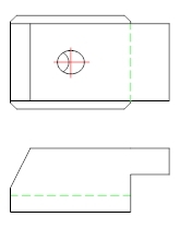
For the undercut of a circular product with sliders on 4 sides, a stop needs to be mounted to the slider insert. It is better to design a separate stop for each individual product if there are multiple products in a single mold.

================================

For simple molded products, ejection often requires a simple motion of ejector pins. These can work with conventional ejection mechanisms. Even complex designs can have very simple ejection mechanisms. The challenge comes with products designed with undercuts. These are parts with holes or grooves on the sides that disrupt a straight part ejection. It would be impossible to eject the product without damaging it in such a case. This sort of product poses an added challenge to the mold maker. It also results in added costs to the process. To address such complexity in injection molding slides get used. This article explains what slides are. It also explains how they work in aiding successful product releases.
The slide feature helps to manage undercuts during product ejection. It is a feature of the mold rather than of the product itself. A mold engineer recognizes the need for slides based on product design. Often the presence of undercuts indicates the need for slides. Manual product removal from the mold might get done without slide features. It works in automated and manual product removal. In much large-scale product manufacturing automated gets used. Automation helps to optimize time and maintain consistency. It also helps meet specific demands such as minimizing hand contact. This might be important in for example sterile manufacturing conditions or sensitive parts. Slides or sliders get used in designs where the mold release direction and that of the product are not the same. Slides no doubt add to tooling cost but they make up for this inefficiency.

Labeled diagram showing the parts of the slide feature
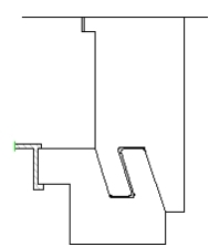
There are several examples of products where slide molds get used. Products with holes, clips, windows, and similar features need sliders. These types of design features make ejection awkward or impossible. In general, products with undercuts. But some undercuts can be unfoldable and have to get removed from the design. These are common candidates for slide mold. The image below illustrates how a product with an undercut is difficult to release from the mold.

Mold with undercuts can’t get ejected from the mold without sliders
Sliders introduce auxiliary parting lines that allow part of the mold to get opened. This part releases the molded part. This is then followed by ejector motion for full part release from the mold. The slider motion occurs either before or after the mold opens. It can also happen at the same time as the mold opens. The motion of the slider gets powered by different mechanisms. This depends on the design of the system. It can be by air, spring, or hydraulic cylinder. Sliders introduce parts moving over each other. This could result in abrasion and wear. The surfaces of these components must get treated to prevent wear. This gets achieved by heat-treating with nitrogen by the nitriding process.

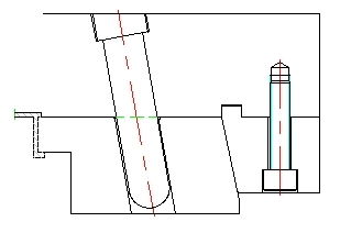
A-The mold closed and guide pin in slide

B- The guide pin moves out of the slide

C- With the pinout of the hole the slide moves and the mold opens
Image A, B, and C illustrating the mechanisms in the injection mold slides.
Below is a flow chart of the slide mold mechanism

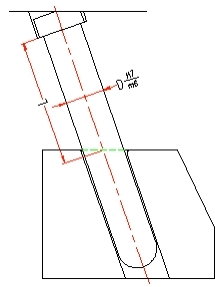
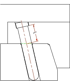
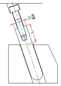
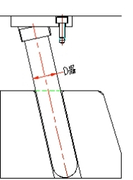
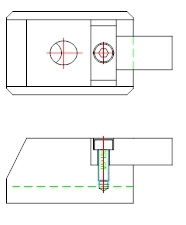
The slide system gets made up of the guide pin, guide block, the slide body, wear plate, and the press block. The guide pin plays a major role in the slide mold. It is the feature used to locate the core and side of the mold cavity. It allows smooth and easy movement in the mold system. It also plays the role of supporting mold weight. Where inserts get used, it protects the core and the inserts. It does this by preventing displacement. The guide pin must be between 15 and 25 mm higher than the product. The slider guide pin is 10 to 15 mm below the mold guide pin. The slider guide pin as the name implies guides the movement of the slide. The diagram below shows the location of the guide pin.
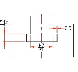
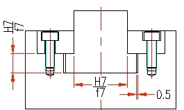
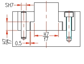
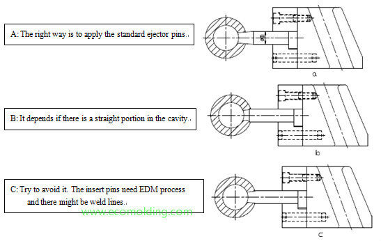
There are different types of guide pins. The type used depends on the type of product and the type of mold in use. There are two key differences between the different types. These are the height above the slide and the lock mechanisms. These get described in the compiled diagrams below.

Image showing different types of guide pin
A- Thin mold plates or clamped plates. Gives good stability and surface matte
B-For 2 or 3 part plates with thick plates and large mold cavity Length to diameter ratio of pis is 1.5 or higher
C- Works well for thin separable mold plates. Gives good stability and matte.
D- For 2 or 3 part plates with thick plates and large mold cavity Length to diameter ratio of pis is 1.5 or higher. The downside of using this type is poor stability and processibility
The guide pin or angular pin fits into the slide block. This is also known as a slider. The slider works in tandem with the guide pin to ease the vertical and horizontal motion of the system. The slider gets supported by another key feature, the guide block. The wedge or guide block exerts a force on the guide pin. It gives it the strength to keep in place despite mold pressure. It also guides the motion of the guide pin.
The slider moves in a perpendicular direction to the guide pin. There are different lock mechanisms that can get used to locking the slide. The general goal is to ensure that the slide locks in place when mold gets shut. When the cycle ends and the product is ready for release, the slider glides off. The distances the glider travels align with the motion of the pin in and out the hole.
Where products with undercuts are present, mold slides become necessary. They enable the removal of otherwise impossible to eject molded parts. Slides introduce added cost to the injection molding process. It requires complex tooling to ensure efficient product release.