The slider for plastic injection mold
Basic Principles of the Slider
Due to the special requirements of a product, the mold release direction of a particular part may not be consistent with the mold opening direction of the injection molding machine (product undercut), the slider,also known as slide,is a mold mechanism that is developed to solve the issues with the undercut. The basic principle is to turn the vertical movement of mold opening / closing into a horizontal motion. In order to cope with the situation that the undercut is located in the core or cavity, different structural forms are developed:
Note:
To mold a product with a deep cavity, of which the side wall does not allow a draft angle, but requires a high gloss, the mold structure also needs to adopt slider mechanism.
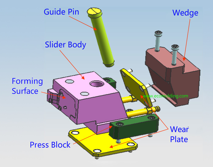
Structural Composition of the Slide
The slide mechanism is usually comprised of the following basic components.
Note:
During slide operation, since the slide, the press plate, the wedge, the guide pin and the wear plate are subject to long-period wear, surface nitriding must be performed to minimize surface wear.
Design of the Angle Pin(Guide pin)
1: How the angle pin locks and where it is used
2: How the Guide Block Moves and Its Design Points
The mold opening action of the injection molding machine is leveraged to make the guide block and the slide move relatively, and surface B engages with the slide to make it move in two directions – the mold opening direction and the horizontal direction, so that it disengages with the undercut. The guide block acts as an angle pin when the mold opens, and as a locking block during mold closing.
See the figure as below:
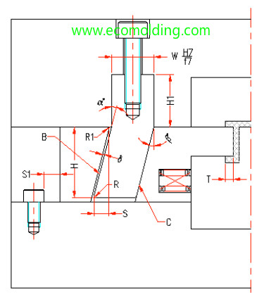
β = α ≦ 25° (α is the tilt angle of the guide block);
H1 ≧ 1.5W (H1 is the corresponding length);
S = T + 2-3mm (S is the horizontal travel distance of the slide; T is the undercut of the finished product);
S = H * sinα-δ / cosα(δ is the gap between the angle pin and the slide, generally is 0.5MM;
H is the vertical distance of the guide block in the slide);
C is the stop surface, so generally a stop block is not needed when the guide block is used (gaps not allowed).
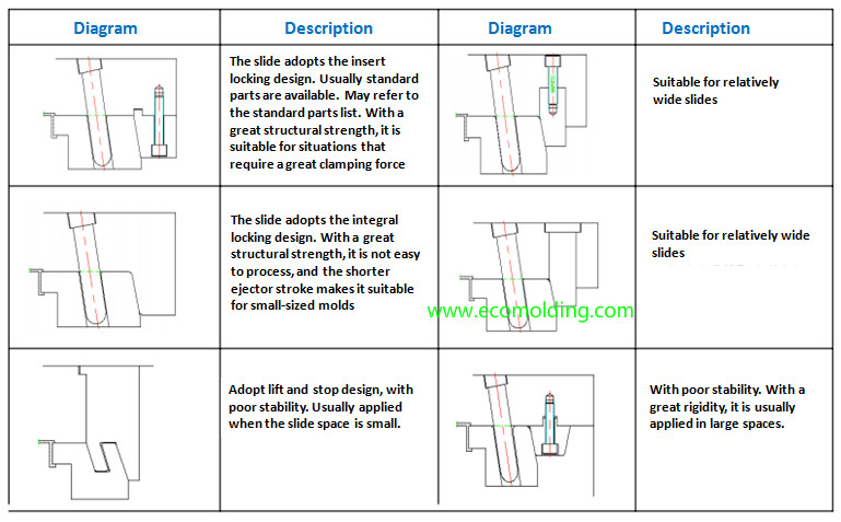
How the Slider Locks
Since great pressure is generated during the plastic injection molding process of a product, to prevent the slider from being displaced by the pressure, which may affect the dimensions and appearance of the finished product (such as flashing), the slider should be locked.
Commonly seen locking methods are shown below:
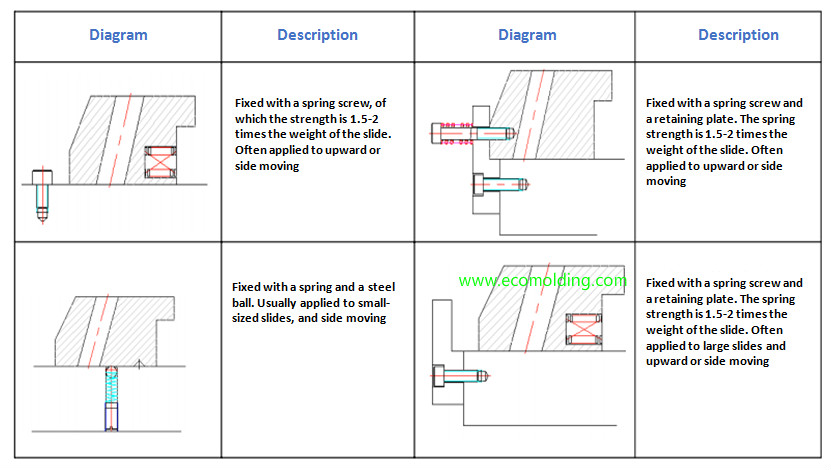
How the Slider Is Located
The slide travels a certain distance during mold opening. Therefore, to guarantee safe slider return, the slider must be equipped with a locking device, which needs to be flexible and reliable to ensure that the slide stays where it is. However, in some special cases, a locking device is not necessary, such as the slider that moves from left to right. But to ensure safety, it is better to have a locking device installed.
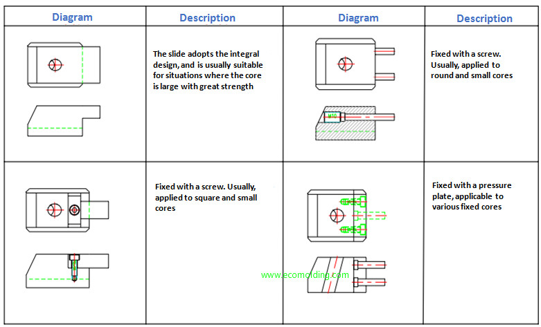
How to Connect the Slider Insert
The connection method for the slider insert is determined by the finished product, since it may vary with different products. The specific connection methods are shown as follows:
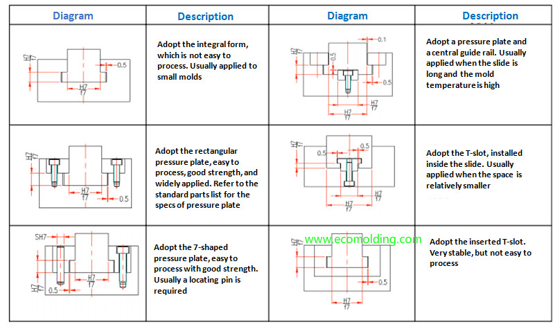
Sliding Guide of the Slide
Sliding guide(sliding rail) has to ensure that the slider moves smoothly and stably, so the slide does not get stuck or bounce during the plastic injection molding process, or product and mold service life will be affected. Sliding guide has to ensure that the slider moves smoothly and stably, so the slider does not get stuck or bounce during the plastic injection molding process, or product and mold service life will be affected.
The commonly used sliding guides are shown below:
The sliders for plastic injection mold


What is guide pin for plastic injection mold?

Guide pin function:
1.Guide pin is for Accurately locate core and cavity side of plastic injection mold,make them match perfectly and move smoothly
2.Support the mold weight
3.Protect core or cavity inserts
Material of guide pin:
SUJ2 ,hardness:HRC 60+/-2 degree.(high-frequency quenching)
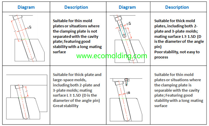
The types and application of guide pin

How to design the length of guide pin?

All copyright reserved by injection mold factory Sositar Mould
What is the stop pin?

The function of the stop pin
1.Reduce the contact surface betwwen ejector plates and clamping plates,it is easy to control the flatness of ejector plates by adjusting the thickness of stop pins.
2.Buffer against ejector plates
The material of stop pin
S45C,hardness HRC40°~45°
Position of stop pin
1.An STP must be installed under the RP to prevent deformation caused by large stress,see pic 1#
2. Avoid to interfere with other mold components,such as support,EGP,KO .etc. see pic 2#
The quantity of stop pins

Note:For a large size plastic injection mold, Stop pin is needed to increase the supporting points of the ejector backing plate, so as to prevent ejector plates from deformation
Injection mold cooling system design
Definition of injection mold cooling system:
Injection mold cooling system: AKA. injection mold temperature control system
Heat or cool the mold to keep its temperature within a reasonable range.
-Mold cooling medium: water, oil, beryllium copper (BeCu) and air, etc.;
-Mold heating methods: hot water, steam, hot oil and heating rod, etc.

Influence of Mold Temperature on Different Plastics
- For plastic materials with great fluidity (PE, PP, HIPS, and ABS, etc.), lowering the mold temperature helps reduce stress cracking (the mold temperature is usually around 60°C);
- For plastic materials with poor fluidity (PC, PPO and PSF, etc.), raising the mold temperature helps reduce the internal stress of the plastic product (the mold temperature usually ranges between 80°C and 120°C).
Influence of mold temperature on quality of molded plastic products
- Temperature too high: The plastic products deform greatly after mold release, and it is easy to cause flashing and sticking;
- Temperature too low: Leading to poor melt fluidity, as well as such surface defects as silver streaks, flow lines, and underfilling;
- Uneven temperature: The plastic products shrink unevenly, resulting in warping deformation.
Mold temperature directly affects the injection cycle
- Injection mold cooling time takes up about 80% of the injection cycle.

Ways to improve mold temperature control
- Appropriate size of cooling lines: diameter 5-13mm (3/16″-1/2″).
- Select mold materials with high thermal conductivity.
- Reasonable plastic product design.
- Proper cooling circuit.
- Enhance the cooling of the thick areas of a plastic product.
- Fast and slow cooling.
- Strictly control the temperature difference between the coolant outlet and inlet.
Key considerations for injection mold cooling channel design
1.Which is more important, cooling or ejection?
2.Try to keep the thermal balance of the mold, so that the temperature is uniform in each part of the mold.

3.A parallel cooling channel is not preferred

Location of cooling lines:
1.Try to keep a consistent distance between the coolant and the filled plastic in the cavity, 10-15mm is preferred. The center distance of the coolant is about 5D.
2.The cooling lines should not be close to locations where the melt flows finally meet;
3.Prevent the cooling lines from interfering with other mechanisms in the mold, and maintain a steel part of 3mm in the middle;
4.The coolant for cavity insert should be as close as possible to the filled plastic, and that of the core insert should be set as far as possible to the outer edge. When the mold cavity / core is too big, the coolant must be in contact with it.
5.For the BeCu mold, coolant may go straightly between plate A and plate B.
Coolant channel length design
The longer the coolant channel, the more difficult it is to process and the worse the cooling effect. The number of cooling line elbows should not exceed five.
The distance between the hoses should not be less than 30mm

O-ring design
1.When the cooling channel passes through two inserts, a O-ring is added in the middle;
2.Try to avoid wear and shear on O-rings during assembly.

Empirical identification of injection mold cooling line diameter:
Mold width < 200mm: diameter 5-6mm (or φ3/16″-1/4″);
Mold width between 200 to 400mm: diameter 6-8mm (or 1/4″ – 5/16″);
Mold width between 400 to 500mm: diameter 8-10mm (or 5/16″-3/8″)
Mold width > 500mm: diameter 10-13mm (or 3/8″-1/2″)

Mold core cooling
1.Core diameter ≤ 10MM: natural cooling;
2.Core diameter between 10 to 15mm: cooling with inlaid BeCu;
3.Core diameter between 15 to 25mm: jet cooling system;
4.Core diameter 25-40MM: cooling bladder + spacer

5.When mold core diameter is greater than 40mm and the height is less than 40mm, it is inconvenient to guide the coolant through to the center, so cooling from the lower surface is recommended.
6.When mold core diameter is greater than 25mm, cooling from the outer side can be adopted when it is inconvenient to guide the coolant through to the center.

===============================
Angle Guide Pin-Slider Components
How to design an angle guide pin?
- The length of the angle guide pin is dependent on slider travel distance, usually a rounded number (5 times); a pocket hole needs to be set up on the mold plate since it’s longer than the slider;
- The angle of an angle pin cannot be larger than 25°;
- The angle pin hole on the slider is referred to as the pocket hole, with a clearance of 0.5mm of both sides and rounded off with a fillet;
- A slider can only be equipped with 2 angle pins at the most, which need to be distributed evenly;
- Slider travel distance = the distance between ① fillet tangent at slider pocket hole and ② the arc tangent at the bottom of the guide pin;
- The angle pin usually uses the same material as the ejector pin; when the diameter is lager than 20mm, the guide pin material will be applied.
How to fix the angle guide pin

Wear Plate-Slider Components of plastic injection mold
Wear Plates
- The purpose of wear plates is to reduce the friction caused by slider movement, ensure smooth slider movement and thus increase mold service life;
- There are 2 types of wear plate: ① bottom wear plate and ② back wear plate;
- 5mm higher than the mold plate, the bottom wear plate is fixed on the mold plate and has direct contact with the slider;
- 0.5mm higher than the slider, the back wear plate is fixed on the slider and has direct contact with the wedge;
- The wear plate usually measures 8mm – 10mm in height;
- The contact area between the wear plate and the slider / wedge needs to be larger than 80%; when the slider is too big, wear plate can be divided into several smaller plates depending on slider size;
- The wear plate applies the SK-3 material, which needs to be preheated.
没有评论:
发表评论