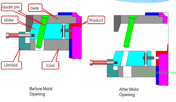
When there are through holes, recesses and bosses, etc. on the side wall of a plastic product which make it impossible to release the mold, the molded product must be moved laterally.we call them undercuts. The entire mechanism that drives the lateral movement of the molded product is referred to as slider or lifter. There are many types of slider, but the most commonly used one is core slider.
According to the deployment of the guide pin and the slide in the mold core, the structure also comes with various forms.
Slide on core side
Slider on cavity side
Inner slider
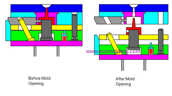
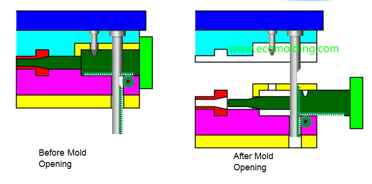
The side core pulling mechanisms, such as the guide pin are only applicable to plastic products with short undercuts. When the undercuts is greater than 80 mm, the Gear driven mechanism is usually employed. In addition, hydraulic driven and spring driven are also very commonly applied.
Hydraulic driven sliders are more expensive, so its application should be minimized, so as to prevent it from affecting the pace and mold layout
Spring driven Mechanism
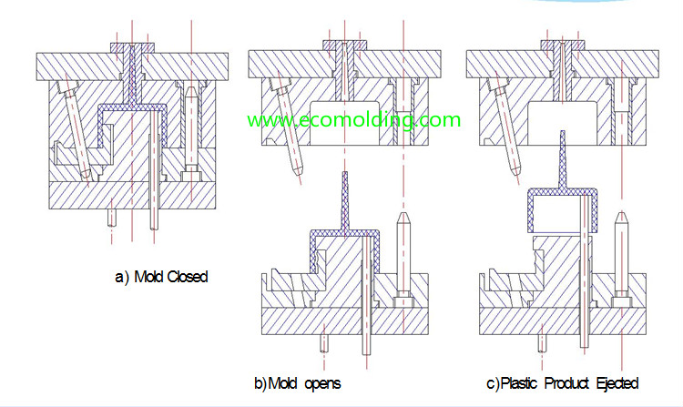
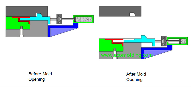
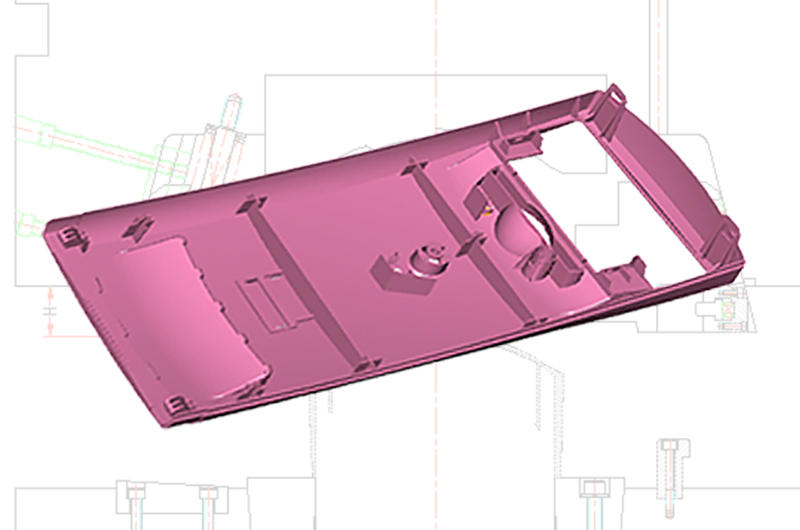
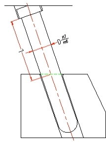
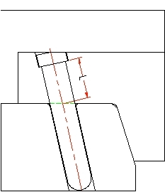
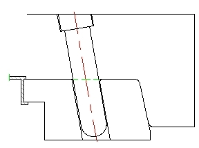
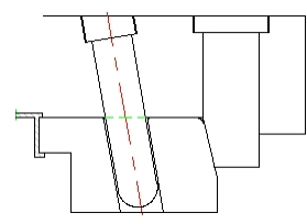
With the oblique movement of the lifter, the undercut is released during the product ejection process.
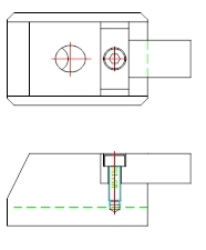
As shown in the figure as below ,the lifter is placed in the angled hole of a fixed mold plate.Give the lifter a push from the bottom up, which moves the lifter up for a certain distance to release the undercts. Now, the lifter not only moves upwards under the forcing of the angled hole and the push, but also moves a certain distance in the direction that the lifter inclines
Some way to remove undercuts in plastic injection mold
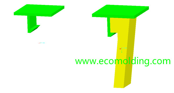
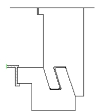
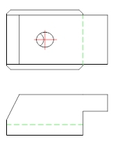
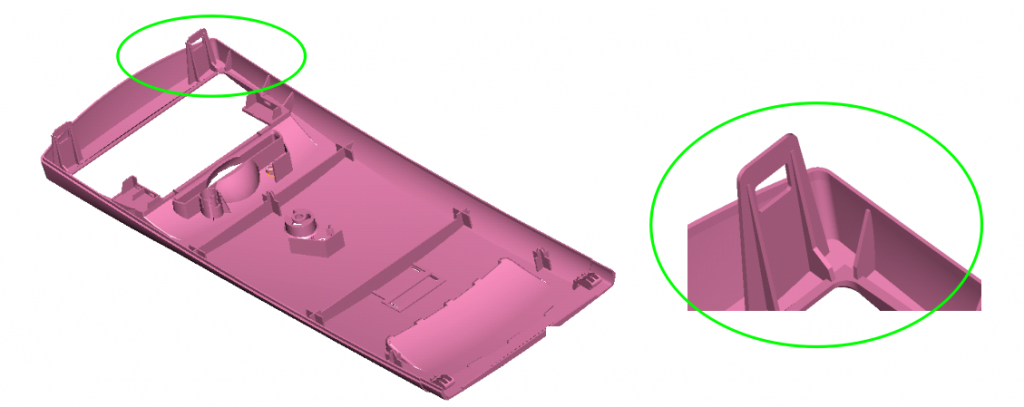
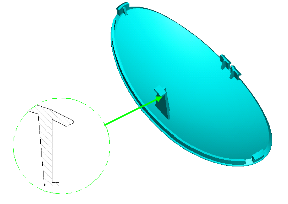
When the customer accept a design change,we have easy way to release the undercuts,For example:we may need a slider or lifter to release the hook as picture show:
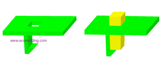
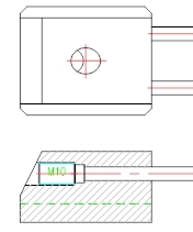
but if we make a cut on top,then we can easily remove the undercuts,and we just need a insert.it will save a lot of time and money.
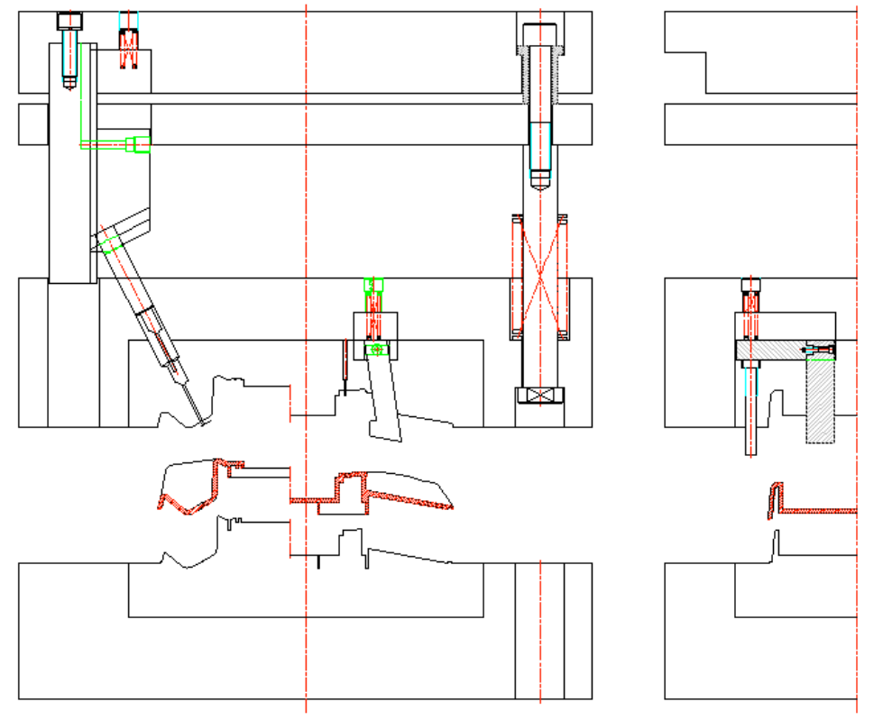
Due to special requirements of product, stripping direction of a certain part is inconsistent with mold opening direction of injection machine, side splitting and core pulling are required to smoothly eject product. There are two types of side splitting and core pulling mechanism: slider and lifter.
First, slider
1. Slider calculation (example below): In order to ensure smooth demould of product, distance of movement of slider must be sufficient. Generally, minimum distance that product can be demolded plus 2~3mm is taken as minimum stroke:
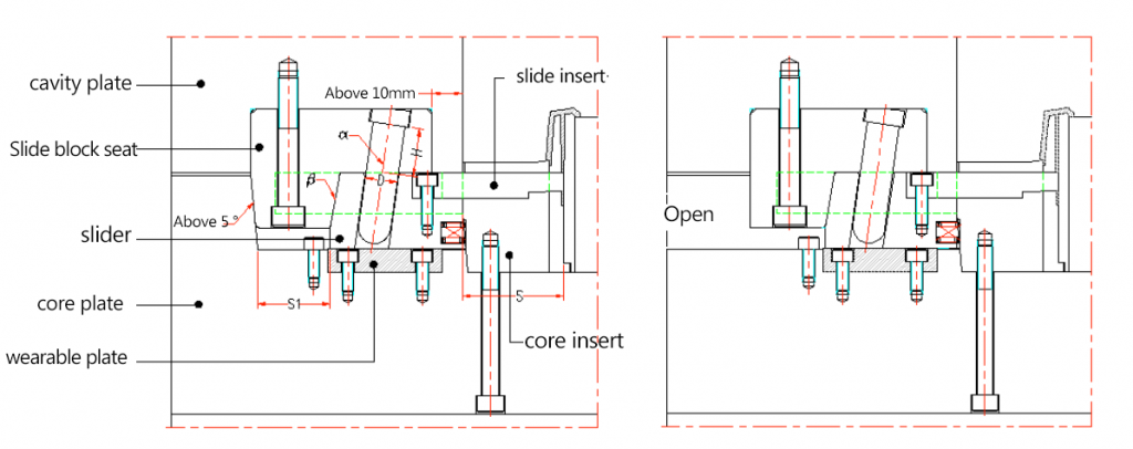
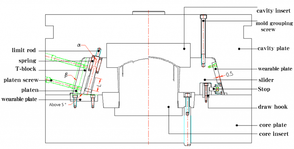
2. Structure of back mould is in the form of press block + oblique pin + slingshot as shown in the figure (sometimes when slider width exceeds 100, and it is not convenient to use this structure, T block structure can be considered). However, when slider is in the direction of up and down, it is limited by position of return needle and size of mold, it can be made from original steel rather than briquetting.
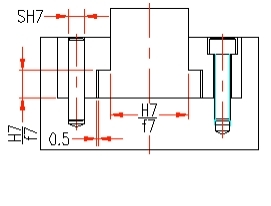
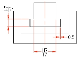
3. Relationship between bottom, top surface of slider and that of mold, see as blow:
4. Regardless of whether there is sealant on the side of slider, slope should be inclined on both sides. General value is 3~5° on one side, but angle is 45° when two sliders are perpendicular to each other. If product has sliders for four sides, designer should consider extending one of sliders to ensure accurate positioning.
5. Ratio of height of slider to thickness is at most 1. Otherwise, movement of slider will be affected by turning moment, resulting in motion failure. Generally, L≧1.5H is required.
6. Angle of oblique pin of slider is generally 15 ° ~ 25 °, maximum can not exceed 25 °, angle of oblique pin is 2 ° smaller than slider, generally try not to use a small oblique pin to ensure smooth movement of slider. 7. Oblique pin hole is 1/64" larger than single side of oblique pin, about 0.4. When oblique pin passes through slider, it needs to leave enough space on template. 8. Position of oblique pin in slider: oblique pin is placed in middle position of slider as much as possible. Specific size requirements are as follows:
9. Matching surface of wedge and slider is required to exceed 2/3 of height of slider, and screws used for wedge should be as large as possible. Following figure shows wedge of two different structures, try to avoid structure of Figure b.
10. Length of slingshot in slider should be determined to ensure that space is sufficient to prevent from failing. Set stroke of slider to M, total length of slingshot is L, and set spring compression to 40%. After slider is completely exited, slingshot is still preloaded by 10%. (40%-10%) L=M L=(10/3)M Slingshot space is 0.6L 11. However, when L is too small, in order to prevent slingshot from failing, it is often necessary to increase length of slingshot.
When slider completely wraps side of product, in order to prevent component from being scratched during movement of slider, a side top device is required on slider, and its structural form is as shown in the figure: in the design, appropriate structure should be selected according to whether mold space is sufficient. It is recommended to use structure of Figure a.
12. In order to make movement of slider smooth, there should be no sharp corners that hinder movement Generally, corners of R3~R5 should be inverted. 13. When installing slingshot under slider, size requirements are as shown in the figure. To prevent screw from being caught by slingshot, refer to table when selecting slingshot and screw.
14. Large sliders should be cooled separately, and wear blocks should be placed on sliders or wedges. At this time, sliders or wedges are avoided by 0.5, as shown.
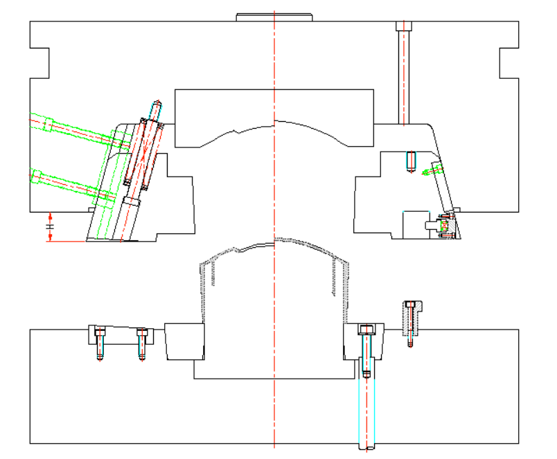
15. When limit slot is to be set on slider of front die, structure is as shown in the figure, h is determined according to slider stroke (attaching limit block size). Limit block is fastened with at least M3/8" screws.
Sometimes, when front mould slider is too small, T block guide is not used, and limit block guide and positioning are directly used.
16. In front mould slider, T block and T slot are avoid by 0.3~0.5 on one side, and only one side is mating surface. As picture shows:
17. Calculation of length of front mould slider slingshot. Set slider stroke M, total length of slingshot L, 40% compression, 10% preload after slider is completely exited, slider angle α, total height of slider H, then: (40%-10%) Lsina=M L=10M/3sina At the same time it should be checked: 0.3Lcosa < 1/2H, otherwise angle should be increased, but maximum should not exceed 25 °, sometimes to prevent failure, often to increase size L. 18. Front mould slider must have slider pull. 19. Front mould slider is changed to T block to be in slider, and T slot is set on wedge.
20. Front mould slider generally requires wear block to be set, as shown in the figure. At this time, mating surface of front mold and slider avoid 0.5 mm.
21. Front mould slider must not exceed 1/2 of total length of slider as shown in the figure.
22. Front mold inward slider, product is required to set front mold inward slider, as shown in the figure. At this time, in order to avoid problem of excessive A-plate avoidance, T-block is often placed in slider, and T-slot is set on slider. 23. When “V” type oil groove is opened in slider, direction of slider should be inclined. “O” shaped oil groove should be perfectly coherent, oil groove depth is 0.5-1.00mm, and oil groove is not open to prevent oil leakage. . 24. Parts with mutual movement on slider are quenched. For example, limit blocks, beading, and so on.
Second, lifter
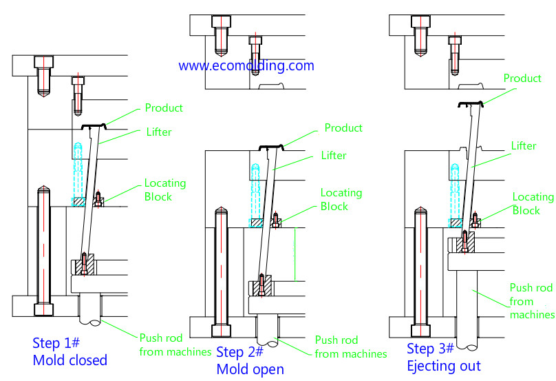
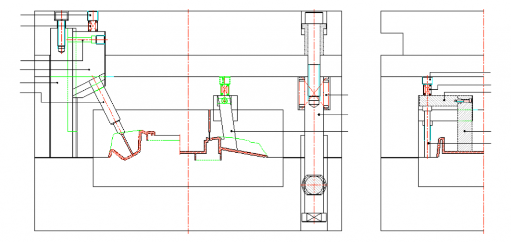
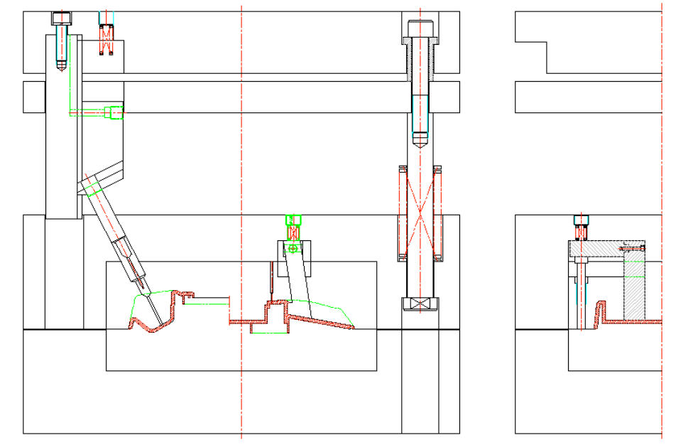
Use of a lifter is often a very effective method when there is an undercut on inner surface of side wall or inner surface of top end of products. Working principle is as follows: while product is being ejected, it is restricted by bevel and simultaneously moved laterally to demould product. 1. Angle of lifter is generally 5°. Size depends on stroke and ejection space. Sometimes C plate is raised to ensure ejection. 2. Minimum thickness of slider is 8.00. In most cases, it can be appropriately increased to 10~15mm. At the same time, slider should be equipped with wear blocks to ensure accurate positioning.
3. When product arc is required to set lifter, processing method is shown in the figure:
4. Lifter is fixed by T seat and screw, and minimum screw is M3/16".
5. When size of lifter and height of ejector are limited by surrounding bone position, boss, or distance between two lifters, solution is to set limit ejector and communicate with design department to change product. 6. Limit ejector mechanism, basic form of limit ejector mechanism is shown in the figure, generally two. H is set according to limit ejector height.
Things you need to know about how to design of mold slide.
Posted on : March 11, 2022 By GREFEE
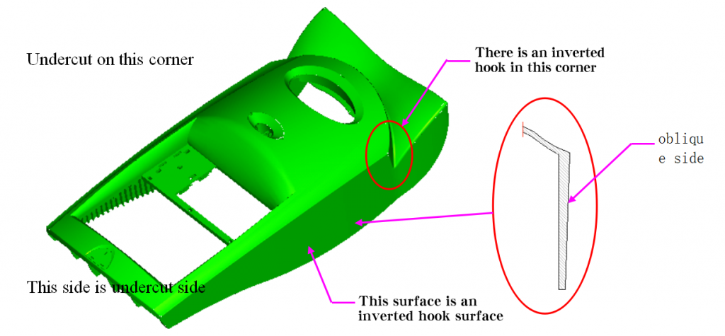
Undercuts treatment
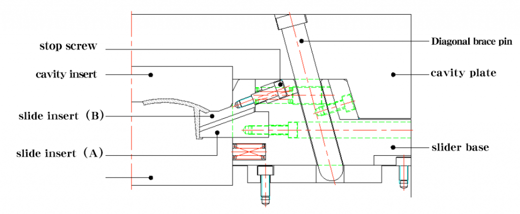
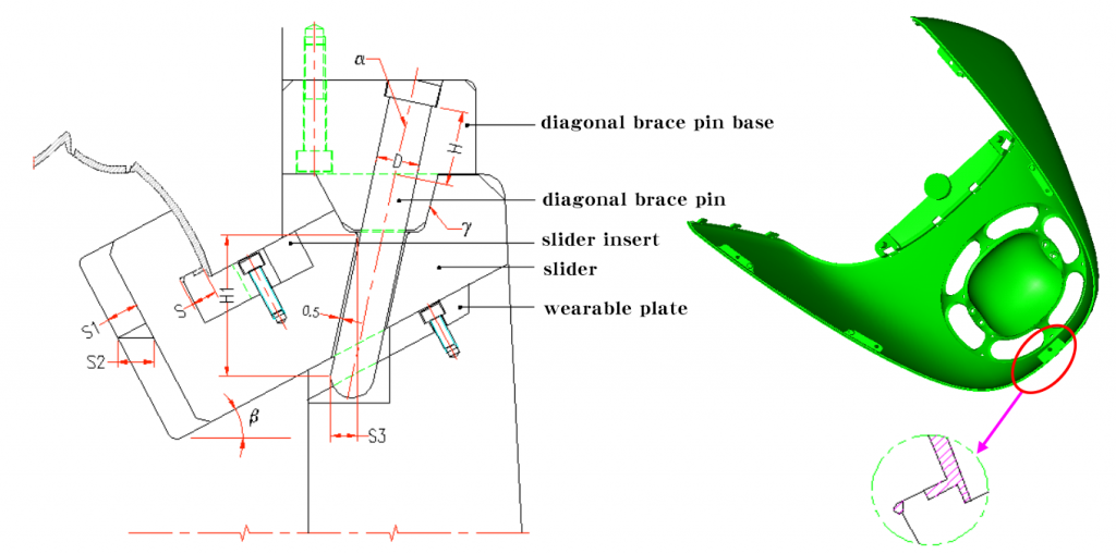
Movement principles & design elements of diagonal bracing pin block
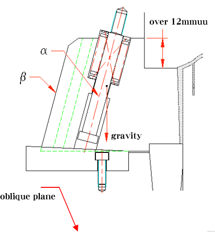
Undercuts treatment uses the mold opening movement and ejection force to causes the tendency of relatively motion between angle pin and slider. There are two movements to make it separate from the undercut : mold opening direction & horizontal direction. As the below pic shows:
in the pic:
β=α+2°~3°(avoid any parts contacts or blocks when group molding & reduce friction when opening molds)
α≦25°(α is the obliquity of taper pin)
L=1.5D (L is matching length)
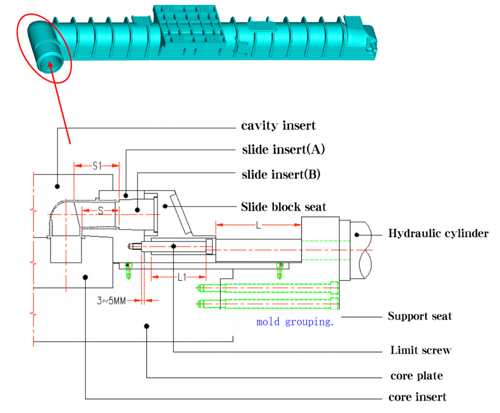
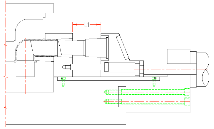
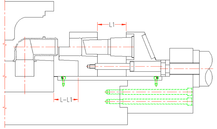
S=T+2~3mm(S, the distance of horizontal movement of slider, T, the end product undercut
S=(L1xsina-δ)/cosα(δ – the space between taper pin and slider, normally is 0.5MM,L1is the taper pin vertical distance inside the slider)
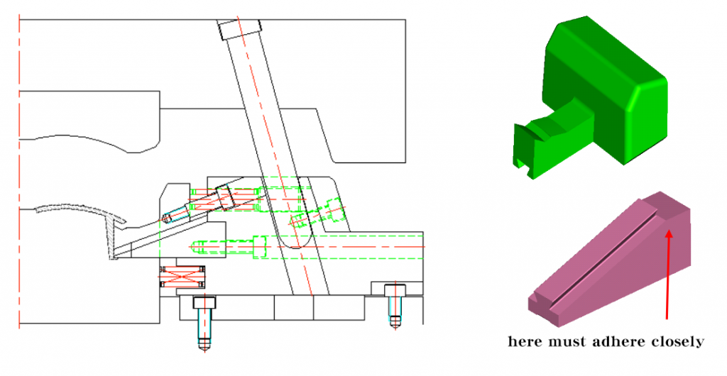
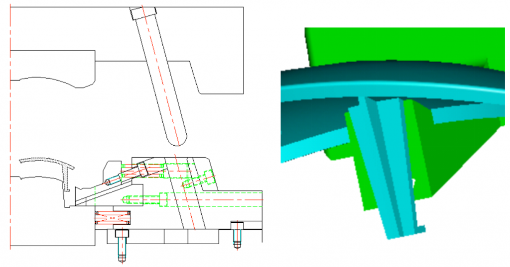
Clamping methods & applicable situations of diagonal bracing tip
Diagram
Description
Suits for situations, like thin mold and the top clamping plate and cavity plate are closed. The contact area is long and stable.
Suits for situations, like thick mold, large mold cavity. applicable to two plate mold/three plate mold.The contact area L≧1.5D(D is diameter of diagonal bracing tip), good stability
Suits for thick mold applicable to two plate mold/three plate mold contact area L≧1.5D(D is diameter of angle pin), poor stability, hard to processing
Suits for situations, like thin mold and the top plate mold and cavity plate can be separated. Long contact area, good stability
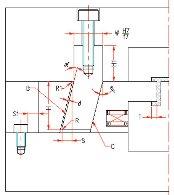
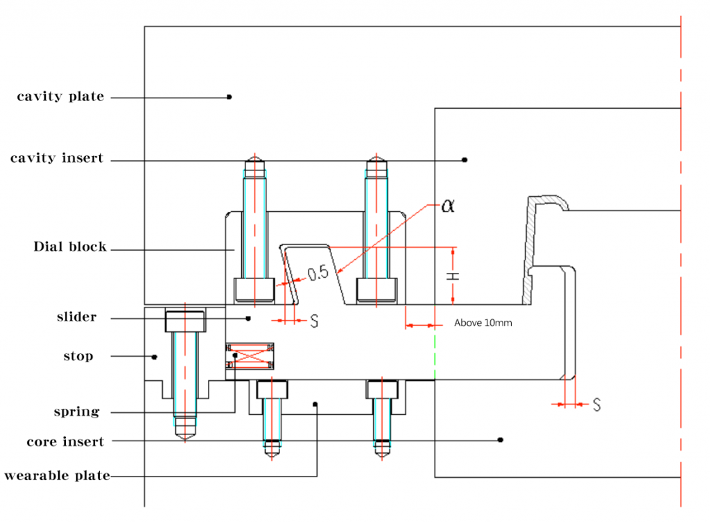
Movement principles & design elements of pulling block
The mold opening movement of molding machine causes a tendency of relatively motion between pulling blocks and sliders.
See pic below:
in the pic above:
β=α≦25° (α – the obliquity of pulling block)
H1≧1.5W (H1-matching distance)
S=T+2~3mm (S-distance of horizontal movement of slider, T- end product undercut)
S=H*sinα-δ/cosα(δ – the space between diagonal bracing tip and sliders, normally is 0.5MM,L1is the vertical distance of
H-vertical distance of pulling block inside the slider)
C- motion stopping surface so the pulling block form doesn’t need motion-stoping surface(no space)
Slider locking & fixing solutions
There is a huge pressure during the molding machine injection process. To avoid affecting the side and appearance(eg. burrs) of end products, we should keep the slider and core unmoved when molding machine injection. So the slider should use locking fixed method to keep it stay. normally, this part is motion-stoping block or heel.
Some common locking methods:
Diagram
Description
Diagram
Description
The sliders are pieced together, normally used for standard products. Normally used standard products, check standard parts catalogue. Good structure and hardness. Applicable to situations needing strong locking force.
Use insert mode to lock. Applicable to wide sliders.
Use integrated locking mode. Good rigidity and structure. Hard to processing. Short Demolding distance. Applicable to small molds
Use insert mode Applicable to wide sliders
Pulling or stopping Poor stability Applicable to situations of small slider space
Are pieced together Good rigidity Applicable to situations of large space
Fixed methods of slider
The slider will move a certain distance in mold opening. One way to make the slider return back smoothly is to use equipment to fix it and it should be flexible and stable so that the slider will stay at where it should be. Some exceptional situations do not need fixed equipments, like left to right slider, so it is suggested to apply a fixed equipment.
Equipment for fixing: diagram
Description
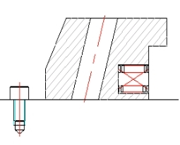
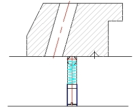
Fixing slider with spring screw, the strength of spring is 1.5-2 times the weight of slider. Applicable to upward or lateral core pulling.
Fixed by spring steel ball. Normally for small sliders for lateral core pulling.
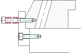
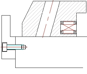
Fixed by spring screw and guard. Strength of spring is 1.5-2 times the weight of slider. Applicable to upward and lateral core pulling.
Fixed by spring guard, Strength of spring is 1.5-2 times the weight of slider. Applicable to big slider, upward and lateral core pulling.
Connecting method of slide insert
How slider head insert connected is controlled by end product. Different end products have different connecting methods.
The slider head insert connected methods details:
Diagram
Description
Diagram
Description
Integrated structure Applicable to situations of large cores, good strength.
Fixed by screw. Applicable to situations of cores, round, or cores are small.
Fixed by screw. Applicable to situations of square cores/small or medium cores
Fixed by screw. Applicable to situations of square cores/small or medium cores
Guide form of sliding block
In the slide guiding, the slider must be smooth and stable so that no stutters or beats, which will affect the aspects, like quality and service life of mold. (Link for the specifications of platen)
The common sliding guide forms are shown in the figure below.
Diagram
Description
Diagram
Description
Integrated manufacturing mode, hard to manufacture, applicable to small mold manufacturing.
Clamping plate ¢ral rail mode. Applicable to situations of long slider and high cavity temperate.
Rectangle platen. Easy to manufacture. Fine strength, wide range of application, the specifications of platen is on standard parts list.
“T” groove inside the slider. Applicable to situations of small space, like slide inside the slider.
Applied “7” shaped clamping plate. Easy to manufacture, good strength. normally fixing with pinhole together.
Inserted “T” groove, good stability, hard to manufacture.
Calculation of tilt slider index
Due to the undercut surface of the end product is tilt, so the move direction of slider should follow the direction of end products’ undercut surface, otherwise it will cause damages when pulling the end product.
When the angle situation between the slider core pulling and the parting surface is called the slider pulling direction moving-die.
Shown as pic:
Situation when the angle between slide core pulling direction and parting surface is slider pulling direction fixed-die.
Shown as below:
master mold runner slider
application features:
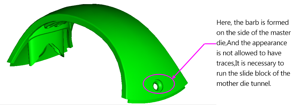
Undercuts forming on the side of master mold
Marks are allowed on the appearance
Medium slider forming area
Shown as below:
Undercut forming on the side of master mold. No marks allowed on appearance. Need to switch to master mold runner slider.
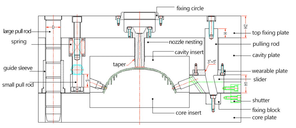
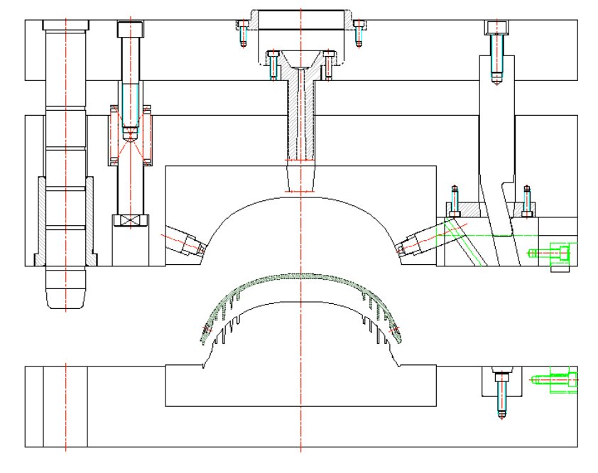
Master mold tunnel block shown as below:
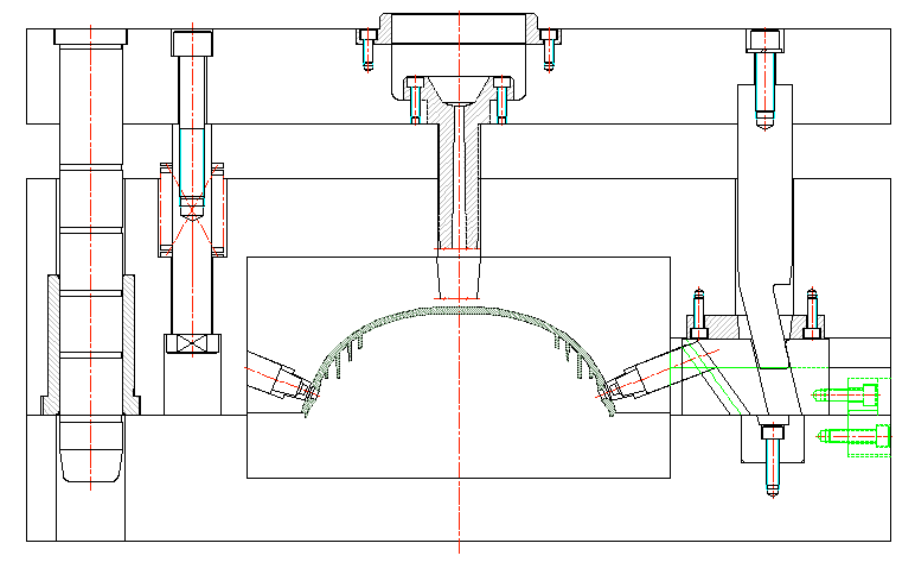
gst mold opening:
second mold opening:
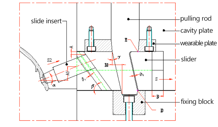
second mold Designing tips
a. Thickness of top clamping plate H2≧1.5D (D – diameter of large tie rod; hyperlink of large tie rod diameter calculation, three play mold large tie rod calculation; H2- thickness of top clamping plate).
b. Depth of pulling block inserted on the top clamping plate H≧2/3H2
c. There should has taper on SPRUE BUSHING head to fit for clamping and should be on the top clamping plate to avoid brush nozzle on the molding machine separating from SPRUE BUSHING and then result in brush, which is inconvenient to take out and affects next injection.
d.when pulling block inside the cavity plate, should reduce material.
e.The wearable plate should be 0.5mm higher than master mold plate to protect the taste mold plate and support the support pulling block to prevent it from distorting due to the external force.
f. Small pull rod limit stroke: S≦2/3H1 assist with mold clamping. (H1 – height of the slider)
g. It is best to have fixed block on the front of pole, easy to adjust and processing, consist three point bearing, increase the strength of pulling block.
h.To make the wearable block assemble smoothly, E point should on the right of D point. Shown as below:
I. When assembling slide base and pulling block, need to notice about the relationship between size B and B1, it shoulbe B>B1, while in order to assemble smoothly, can also dig through the rear mold located after the slide base.
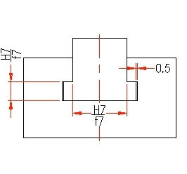
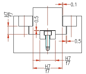
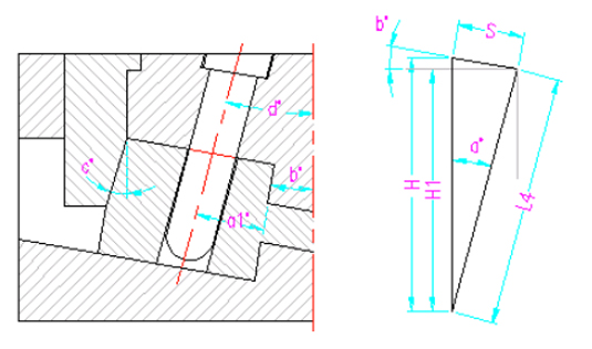
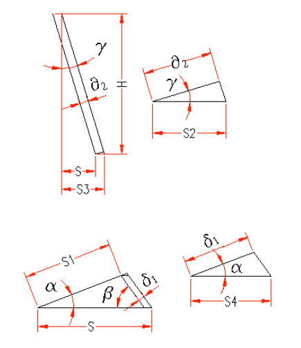
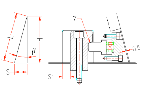
Dos and don’ts & calculation formula of double “T” groove
Shown as above:
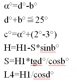
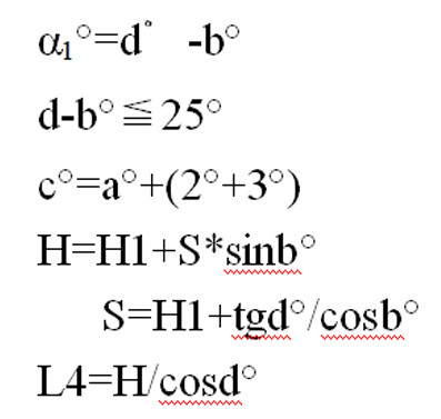
S3=H*tgγ;
(H – the decreased height of slide block which is the small pull rod stroke; γ – the angle of pulling block)
S2=δ2*cosγ;
(δ2 – the space between pulling block and slide block, normally is 0.5mm)
S=S3-S2=H*tgγ-δ2*cosγ=(H*sinγ-δ2)/cosγ;
(S — horizontal moving distance of slide block)
S4=δ1/cosα;
(δ1 – slider insert and space between sliders;α -tilt angle of slider insert)
S1=(H*sinβ-δ1)/sin(α+β);
(β – space between grooves,normally is 0.5mm;S1- distance of slider insert out from the undercut)
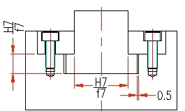
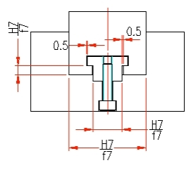
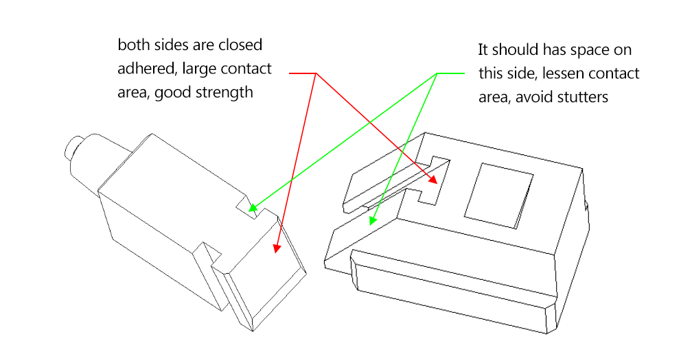
Dos and donts:
a. Assemble requirements: assemble the slider insert and inclined insert hole, it should notice the relationship between the size A and A1, should be A>A1.
b. Double “T” groove tolerance, shown as below:
Case of Assemble matters
Die sketch
pic above :
Slide insert can be put inside the core insert without problems, required S1>S or open the core plate.
β=α+2°~3° (easy to open mold and reduce scratches)
H≧1.5D H is diagonal brace pin matching length; D is diameter of diagonal brace pin)
Double “T” groove structure model:
Double “T” groove structure model:
Cavity explosive slider
applicable situations of explosive slide block
Generally, forming on the cavity side and large slider forming area, especially using slider when the cavity side is very deep.
Explosive slider as blow pic shows:
mold opening state:
Stroke calculation:
Shown in the pic below:
S=L*sinβ (β- “T” groove angle;L stroke along the “T” groove direction; S – distance of slide block horizontal movement)
H=L*cosβ (H distance of slide block vertical distance)
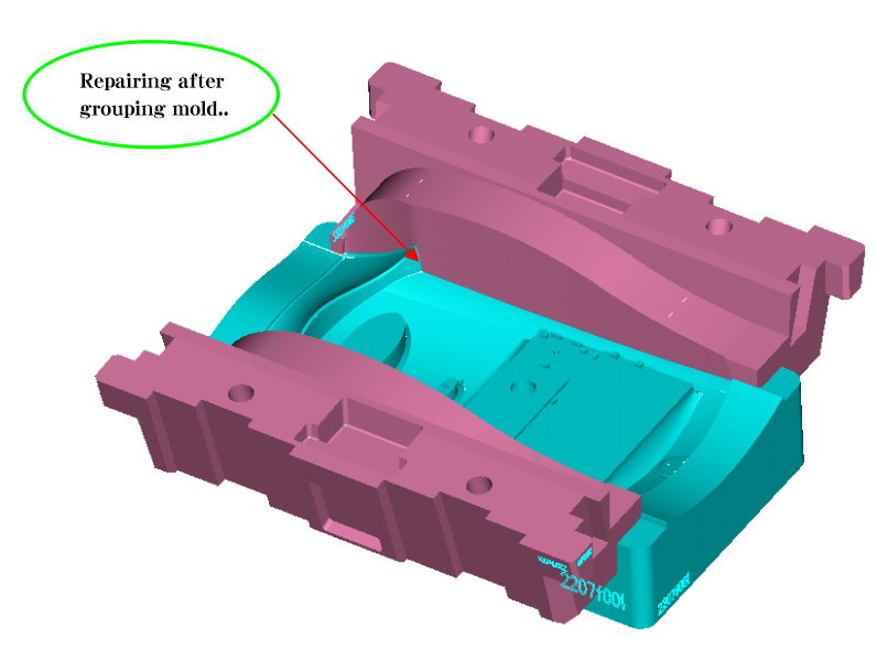
Design tips and notices of explosive slide block
Shown as the pic on the right:
a.bottom wearable plate needs bevel, reduce loss between slide block and core plate, normally takes 1.5˚~3˚, assemble location be at the 3 / 4 of the center of gravity of the slide block.
b.S1>S (S – distance of slide block horizontal movement)
c. the wearable plate on the back of slide block and should be 0.5 mm higher than slide block’s back.
e. The angle between block and grab hook γ> the wearable plate obliquity.
f.β=α (β is “T” groove angle;α is lmit rod angle)
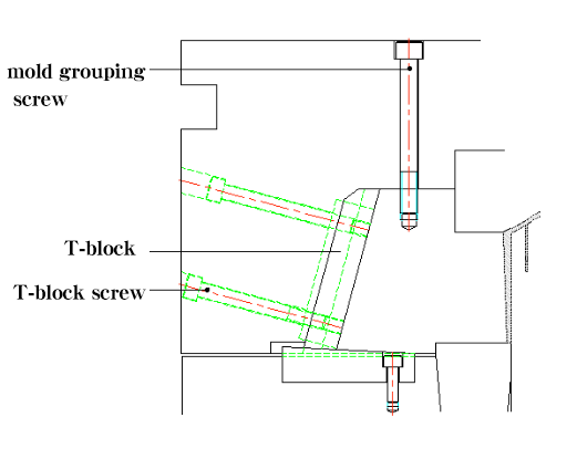
g. T – block should be longer and 10 mm higher than cavity plate.
h. Slide block head should have die screw, easy to group the mold. Need to take down when testing mold
i. Lock T-block screw should be vertical to T block.
j. The spring at the head, should calculate the weight of slide block.
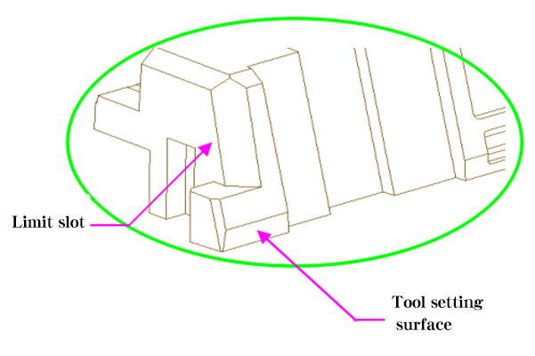
k. The back of the slide block should be tool setting plane.
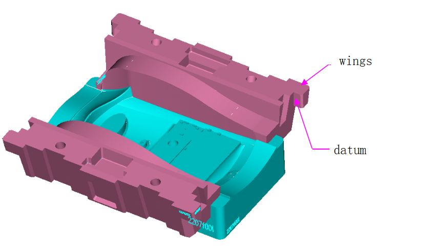
l. Both flanks of slide block should have limit groove.
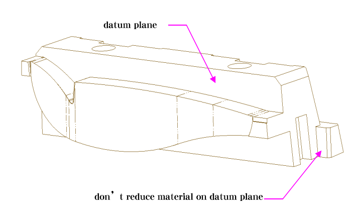
m. The slide block head must have datum plane to provide convenience for grouping mold. The processing base level is normally over 8mm.
n. Explosive slide block must have shoulder (wings for fixing) to provide convenience for grouping mold and also a base level is necessary, cannot reduce the material)
The assemble location depends on the location of the gravity of slide block.
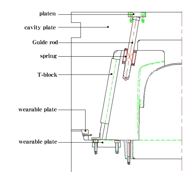
Dos and don’ts of Extra deep explosive slide block
the guide rod should assemble from the cavity plate
a、Cavity plate should be embedded into the core plate,avoid the cavity plate outward lift, enhance the mold strength
b.wearable plates needed at the protruding side of cavity plate, avoid scratches, easy to adjust.
c. Other precautions are the same as above
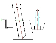
Place ejector pin inside slider
Generally, for thick and deep products’ wall, the side of the wall has many core pulling holes. The core pulling force is strong, so when moving the slide block, the product might be distorted or scratched. To avoid these happening, we need to place the ejector pin inside the slide block to stop the distortion or scratches.
A. Place ejector pin inside slide block (example 1)
B. Two common ways to place the ejector pin inside slide block, shown as below:
Delay slider
1. The outside product pulling force is strong, avoid distortion.
2. Use delay slider to operate forced demolding.
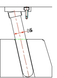
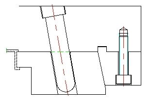
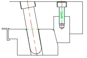
The pic below is water pipe and water pipe delay diagram:
1st mold
Finishing state after 2nd mold opening
oblique slider
1. Application range of oblique slider Normally applied in the products with slider structure, at the same time, along the slider’s direction, the end product also has undercut, which indicates that we can apply oblique slider.
note:
Pic on the right is typical case of oblique slider
2. Oblique slider diagram:
3.internal slider
(1) use boss form (seen as below)
Use the form of diagonal brace pin (as shown below)
In the figure above
S1 = S + 1mm above(S, undercut distance;S1 distance of slider moving
S2=S1/cosβ (S2, horizontal distance of slider;β obliquity of slider)
Calculation of core pulling force & strength checking
1. Calculation of core pulling force
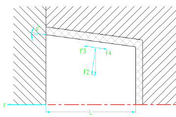
After cooling, the plastic will be narrowing and shortening, including the die core and the other parts (like oblique tip, slider, insert etc)Therefore, we must consider the enclosed strength that end product impact on slider, stress state, see pic on the right
note:
F=F4*cosα-F3cosα=(F4-F3)*cosα
F—core pulling force(N);
F3—F2 lateral component(N)
F4— core pulling resistance(N);
α—obliquity of de-molding. as α is normally low, so cosα=1
That is F=F4-F3
But F2=F1-cosα
F3=F2tgα=F1cosα*tgα=F1*sinα
F4=F2*μ=μ-F1cosα
So F=F4-F3=μ*F1cosα-F1sinα=F1(μcosα-sinα)
F1——the enclosed strength that plastic on core (N)
F2—perpendicular to positive pressure on the surface of core(N)
μ—the friction coefficient between palstic and steel, normally is around 0.2
While F1=CLF.
The average circumference of core cross-section part which enclosed by plastic.
L—the distance of core part enclosed by plastic (CM)
F0—enclosed strength of unit area, normally 7.85~11.77MPA
Namely F=100CLF0(μcosα-sinα) (N)
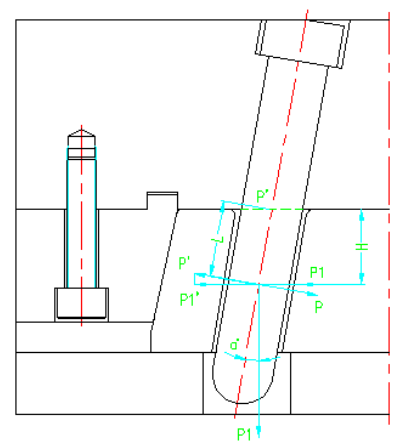
2. Diagonal bracing tip diameter checking:
The diameter of diagonal bracing tip is affected by many factors, like obliquity, length, and required de-molding distance. Thus, in designing, some parameters should be adjusted and matched to obtain the best result to make sure the slider to move smoothly. Calculation formula:
Note:P – maximum bending force on taper pin
L— bending moment
P1—core pulling resistance
H— distance from core pulling hole center to point A