Design of compound core pulling mechanism with built-in inclined top block
With rapid development of economy, automobiles as consumer goods have increasingly entered thousands of households, and automotive molds have also experienced nearly two decades of development. In the context of continuous development of injection technology, automotive industry has become increasingly demanding on appearance and function of plastic products, which puts higher requirements on design and manufacture of injection molds.
1 Product analysis

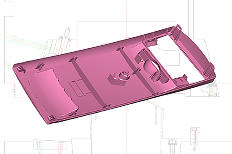
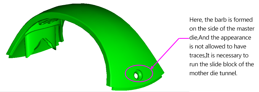
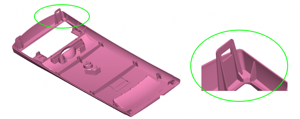
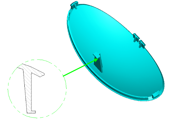
Figure 1 Car handrail
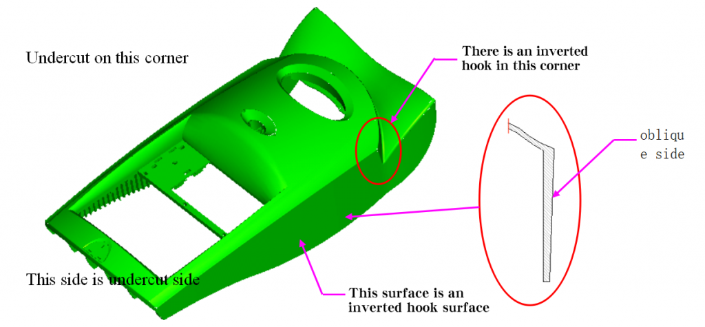
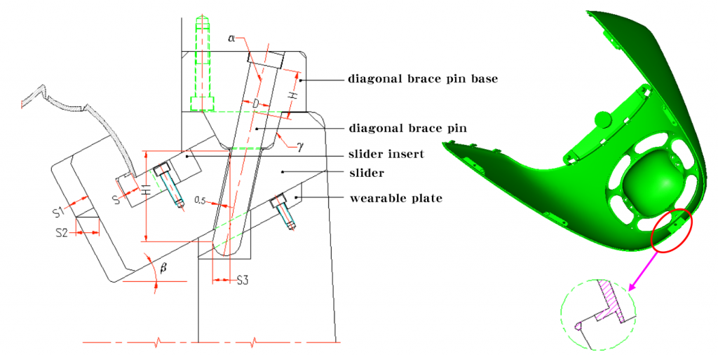
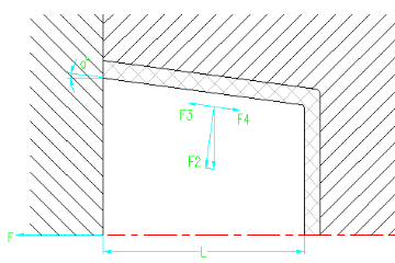
Product is a car handrail, external dimensions are 84.46mm * 249.97mm * 105.08mm, as shown in Figure 1, molding material is ABS, which has good moldability and paintability. Molded product has good surface roughness and high impact strength. Product structure feature is that there are many reverse buckles. There is also a small vertical buckle on large reverse buckle. This feature adds difficulty to design and manufacture of mold. When designing mold, it is necessary to design lifter block in the slider, slider is formed at large reverse buckle, and lifter block is formed at small reverse buckle. Mold opening direction is shown in Fig. 2. Slider is cored and demoulded in Y direction, slider block is cored and demoulded in X direction.

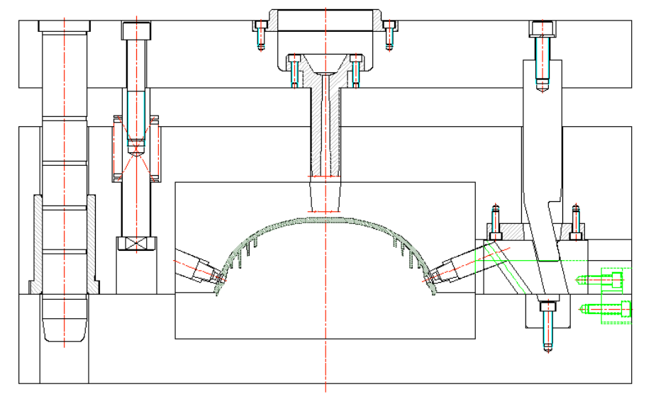
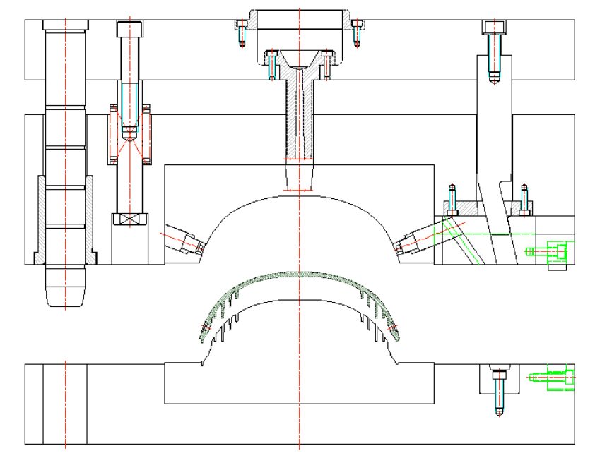
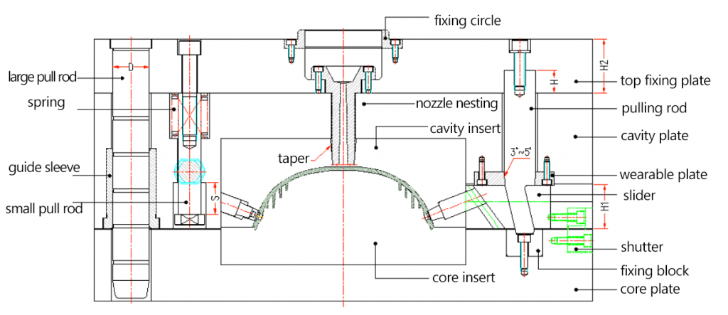
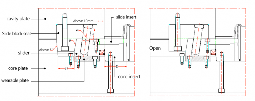
Fig. 2 Demoulding direction of composite core pulling mechanism
There are usually two design schemes for formation of products with similar structures above: ① Install a spring in slider, and use spring force to complete core pulling of lifter block in the slider; ② Lifter block and slider are respectively equipped with a hydraulic cylinder. Core pulling of lifter block in the slider is completed by double power. These two design schemes have shortcomings. The former spring mechanism is unstable, strength of spring will decrease with increase of number of uses. On the other hand, processing position of spring hole will also affect smoothness of movement of lifter block. Mechanism is easy to fail and can not accurately complete core pulling, reduce molding quality of product, or even scrap. The latter double hydraulic cylinder structure occupies a large space, increases overall size of mold, increases manufacturing cost. Compound core pulling mechanism introduced now is simple and stable in structure, low in manufacturing cost, and occupies less space. It can successfully complete core-pulling work and ensure molding quality of products.
2 Compound core pulling mechanism structure
01 Hydraulic cylinder slider mechanism

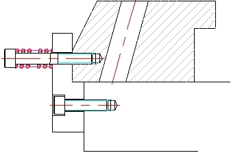
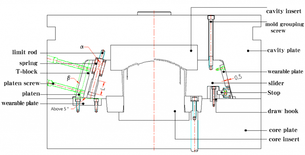
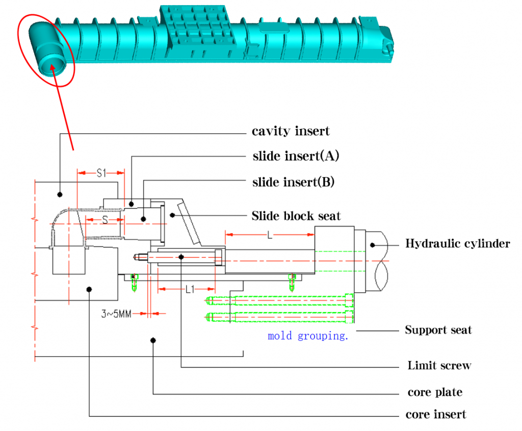
Figure 3 Composite core pulling mechanism

Figure 4 Hydraulic cylinder slider mechanism components
- Hydraulic cylinder 2. T-shaped block 3. Slider

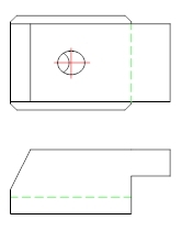
Figure 5 Slider bottom view
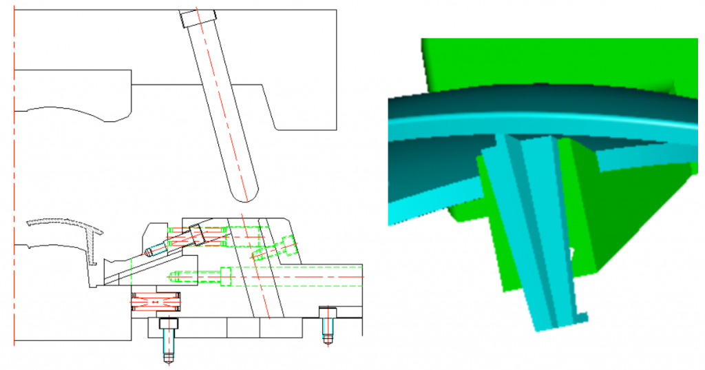
Figure 3 shows assembly structure of composite core-pulling mechanism. Large inverted part of product to be formed is designed as a slider forming. In hydraulic cylinder slider mechanism assembly shown in Figure 4, hydraulic cylinder and slider are connected by a T-shaped block, power is provided by hydraulic cylinder to push slider core to complete demolding and mold closing action of slider in Y direction. Slider is provided with a tunnel and a groove inside. Tunnel is used to install a lifter block. Groove can catch a movable insert that moves upward, as shown in FIG. 5.
02 Inclined top block mechanism

Figure 6 lifter block mechanism components
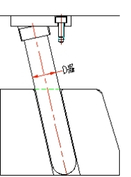
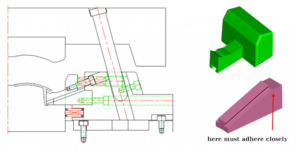
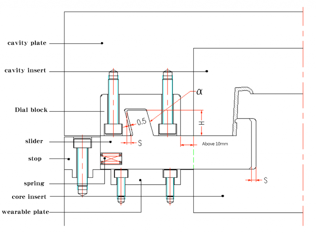
1. Stopping block 2. Wear-resistant block 3. Movable insert set 4. Slanted top block fixing block 5. Spring 6. Movable insert 7. Slanted top block 8. Small inverted parts of pressed product are formed by lifter block. In lifter block mechanism assembly, there is a inclined groove on the stop block, and movable insert can be pushed upward through inclined surface, as shown in FIG. 6. Movable insert sleeve is fixed on fixed block of lifter block to guide movable insert and move with fixed block of lifter block, spring can provide a restoring force for movable insert.

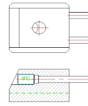
Figure 7 Top view of lifter block mechanism assembly
1. Lifter block fixing block 2. Oblique top block
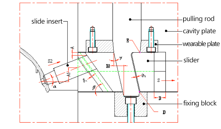
Fixed block of lifter block is designed with a inclined groove. Lifter block can slide back and forth on inclined groove to complete demolding and mold close action of lifter block in X direction, as shown in FIG. 7.
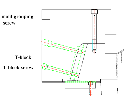
03 Rack components

Figure 8 Rack components
1. Stop block 2. Wear-resistant block 3. Moving template 4. Guide rail I 5. Guide rail II
In Fig. 8, stopper block, wear-resistant block and guide rail II are fixedly installed on moving mold plate, and form a rack system with moving mold plate. Guide rail I is installed on slider, and slider can slide relatively on guide rail II.
3 Process principle
Slider has a built-in composite core pulling mechanism for lifter block, and a tunnel is designed inside slider to install slider block. When mold is opened, piston rod of hydraulic cylinder drives slider to move in Y direction, and slider is detached from large undercut of product. At the same time, slider uses tunnel slope to push lifter block to move in X direction, lifter block is separated from small inverted of plastic part buckle. After a period of movement, demolding of lifter block in X direction is completed, piston rod of hydraulic cylinder drives slider and lifter block to continue to move in Y direction, thereby completing core pulling.
01 Mold opening process

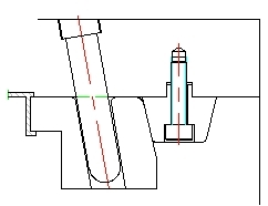
Figure 9 assembly of pressure block and slider
- Press block 2. Slider

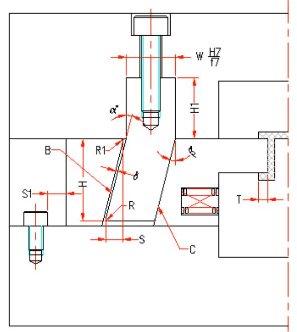
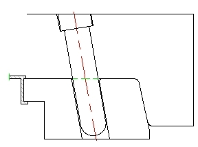
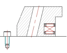
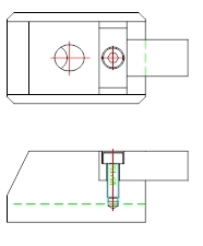
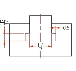
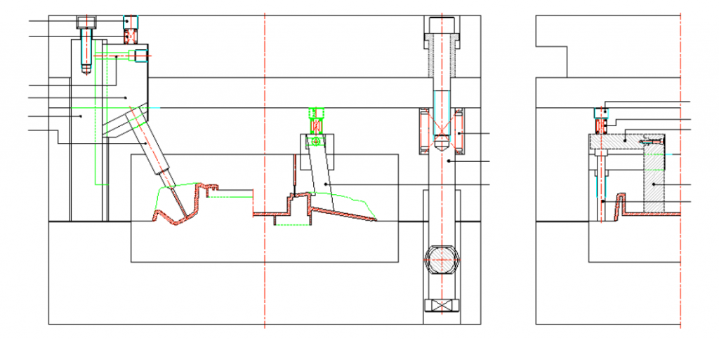
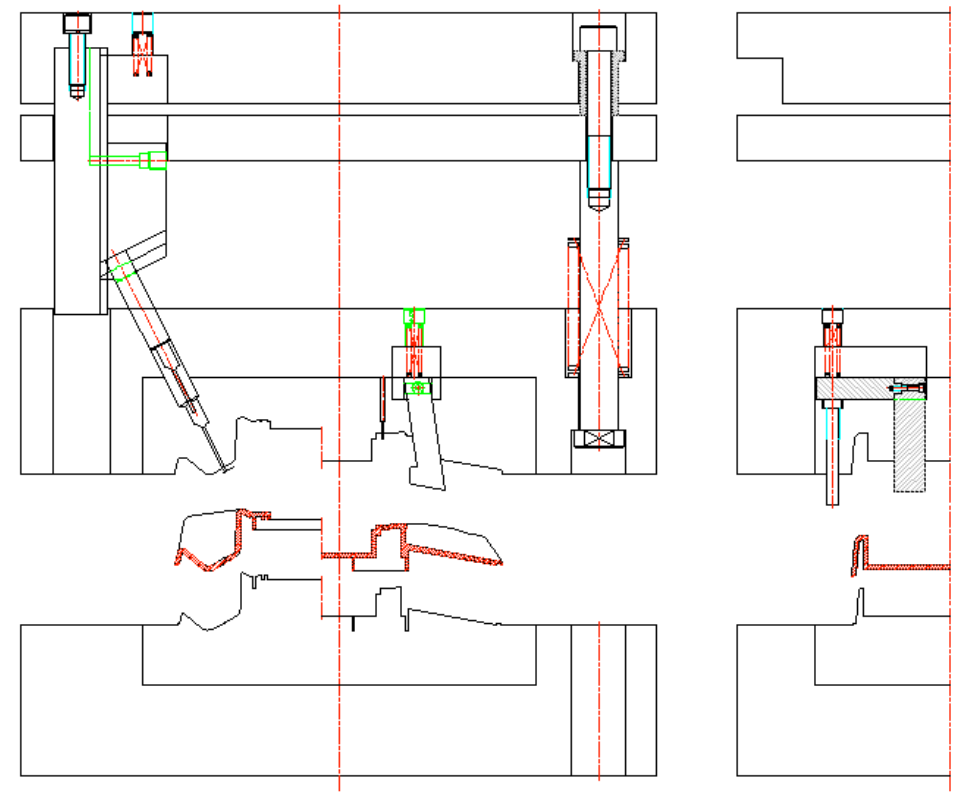
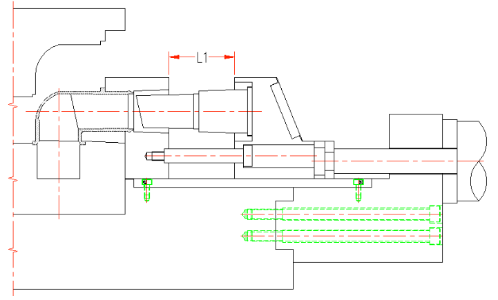
Figure 10 Cross-sectional structure of first stage mold
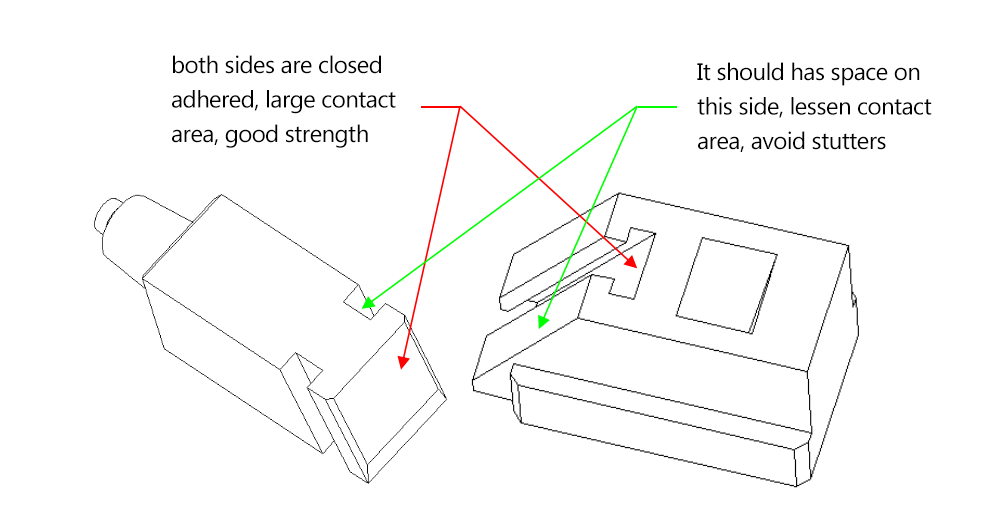
1. Slanted top block 2. Slider 3. Slanted top block fixed block 4. Movable insert sleeve 5. Press block 6. Movable template 7. Stop block 8. Movable insert 9. SpringThe first stage opened. Pressing block is fixedly installed on slider and moves with slider, as shown in FIG. 9. As shown in Figure 10, between slider and fixed block of lifter block, pressing block and hydraulic cylinder of movable insert sleeve drive slider to move 26mm in Y direction first, lifter block moves along X direction of slide groove on inclined surface of slider tunnel and lifter fixed block, slider and inclined roof block simultaneously separate reverse buckling of product. At this time, core pulling of inclined roof block in X direction has been completed. In the first stage of mold opening, chute on stop block catches movable insert, so that fixed block and lifter block will not follow slider in Y direction due to sliding friction generated by movement of slider, lifter block is now holding product, restraining movement of product in Y direction, when anti-slip block is separated from product, product will adhere to slider and move with slider, resulting in defects such as product deformation, damage or unqualified dimensions.

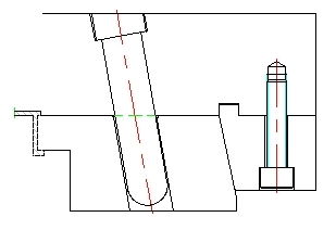
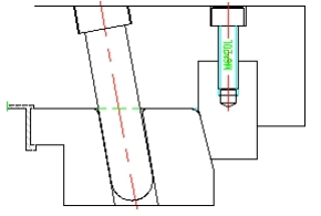
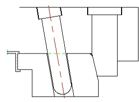
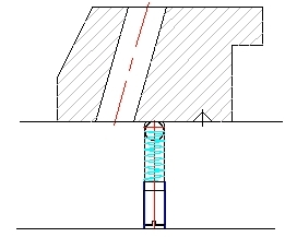
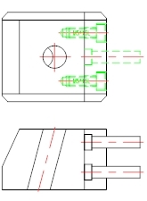
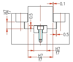
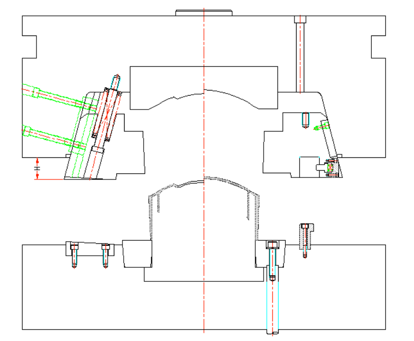
Figure 11 Organization status at the end of first phase

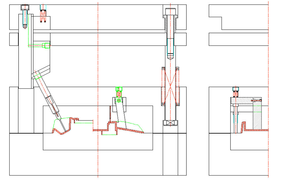
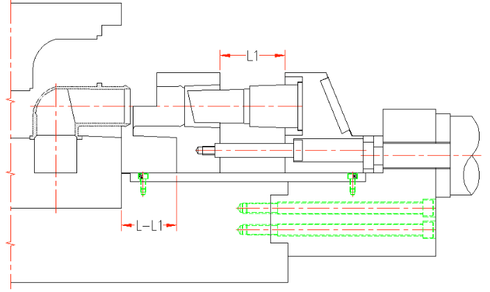
Figure 12 Core section to complete cross-sectional structure of mold
1. Slanted top block 2. Slider 3. Slanted top block fixed block 4. Movable insert sleeve 5. Press block 6. Movable template 7. Stop block 8. Movable insert 9. SpringThe second stage mold opening. Figure 11 shows state at the end of the first stage. After slider moves 26mm, slider and pressing block respectively contact fixed block of lifter block and movable insert sleeve, then slider and pressing block together push fixed block and lifter block to move in Y direction together. At this time, lifter block and slider do not move relative to each other, and lifter block will not move in X direction. During demoulding process of core pulling mechanism in Y direction, movable insert passes through chute of stop block, pushes out along slope of chute, and finally stuck on the insert above slider tunnel, and product is separated to a safe position with core pulling mechanism, and core pulling is completed, as shown in Figure 12.
02 Mold clamping process

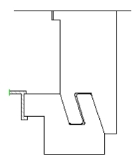
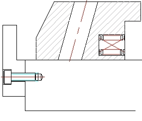
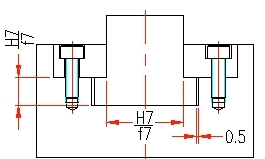
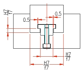
Figure 13 State of mechanism after completing core pulling
State that mechanism has completed core pulling is shown in Figure 13. After taking out product, mechanism starts mold clamping movement. Piston rod of hydraulic cylinder pushes slider and pressing block to move 26mm in -Y direction first. In this process, slider pushes lifter block through tunnel slope to move in -X direction. After 26mm of movement, slider and pressing block push fixed block of lifter block and movable panel piece sleeve to continue to move, and movable insert can return to stop block chute by restoring force of spring. At this point, all components of core pulling mechanism are reset, and mold is smoothly closed to complete a molding cycle.