2022年12月21日星期三

NX shortcut key

 这是最佳答案是慧正外挂.免费的.功能完善.

可以自定义,速度快.....

慧正设计首选项->常规-启用快捷键(CAD操作方式)

定义快捷键是  同一个页面底下有个打开配置目录shortcutKey.txt文件

可以定义.attachments-2020-12-QlcIcPyW5fcc61cbb01d1.jpg

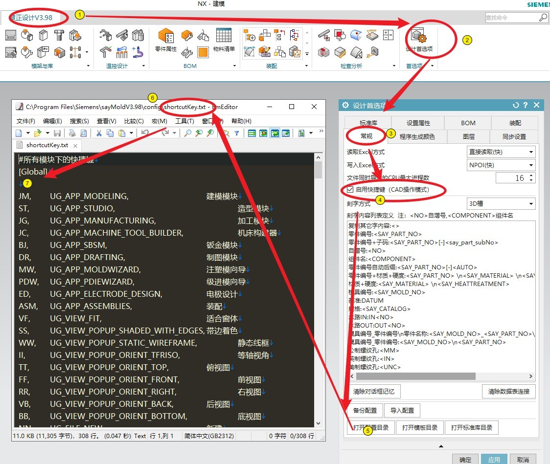
F3D目前不好使..在开发中..其他的也不行..这个最好了

慧正是通过QQ群找的~~!

关闭帖子~!

2022年12月10日星期六

 Display a reference set at all assembly levels

This example shows how the Apply to All Assembly Levels option works with subassembly reference sets to provide different display options for an assembly.

In the following figure, a simple vise assembly is shown as it is saved, with the Entire Part condition displayed for every component.

The assembly contains four subassemblies and some piece parts.

As the example begins, the subassemblies do not have any defined reference sets.

Handle

Piece parts

Moving jaw, including handle

Fixed jaw

Guide

  1. Open the assembly with the Model reference set displayed for every part that has it, and the Entire Part display condition for other parts.

    1. Choose File tab→Open.

    2. In the Open dialog box, click Options.

    3. In the Assembly Load Options dialog box, in the Reference Sets group, arrange the list with Use Model at the top, and Entire Part second.

    4. Click OK.

    5. In the Open dialog box, select the vise assembly part and click OK.

    The assembly is opened with every Model reference set displayed.

  2. Define a Model reference set in the handle subassembly, and in that reference set, use a simplified body to replace the detailed thread in the screw.

    The Model reference set for the screw component has a detailed thread feature.

    It is possible to have so much small detail in components that your display regeneration time is affected.

    The screw part has three references sets, as shown in the following figure.

    Model

    Simplified

    Symbolic

    You can create similar reference sets in any part by constructing whatever geometry you require.

    1. With the handle subassembly as the displayed part, display the Model reference set for all components.

    2. Change the reference set of the screw to its SIMPLIFIED reference set.

    3. If necessary, create a Model reference set in the handle subassembly.

    4. Edit the Model to contain all of the components in their current condition.

      When you add a component to a reference set in an assembly, the assembly level reference set records the reference set that the component is displaying.

      If the components are already selected, deselect all components and then select them again with their currently displayed reference set.

    5. In the Reference Sets dialog box, from the list, select Model and click Information.

      The Information window should show that for the Model reference set, all components except the screw are displayed with their Model reference sets. The screw is displaying its SIMPLIFIED reference set.

      If the components are not displaying the reference sets described, remove the incorrectly displayed components from the reference set, display the reference sets you want for those components, and add the components to the reference set again.

    6. Save the handle subassembly, and close all parts.

  3. Open the vise assembly to display the Model reference set you created in the handle subassembly, with a simplified display of the screw.

    You can use the same steps as you used to open the assembly initially, except this time, in the Assembly Load Options dialog box, you must clear the Apply to All Assembly Levels check box.

    The assembly shows the model reference set for all components except the screw.

    This happens for the following reasons:

    • The handle subassembly has a model reference set that includes the simplified reference set of the screw and the model reference set of the other piece parts.

    • The Apply to All Assembly Levels check box is clear, so the search for reference sets ends at the handle subassembly. The handle subassembly is opened displaying the model reference set that you defined.

    • The other subassemblies do not contain a model reference set, so they are loaded displaying their Entire Part reference sets. The Entire Part is only a display condition, not a true reference set, so the search for model reference sets continues to the subassembly piece parts.

    To open the assembly as it is now saved, and to display the Model reference set for all piece parts, select the Apply to All Assembly Levels check box. Although the subassembly Model reference set is found, each piece part is checked and, if it has a Model reference set, the Model reference set is displayed.

  4. Define a Drawing reference set in the handle subassembly.

    The Model reference set with its detail thread is too complicated for most drawing requirements, and the SIMPLIFIED reference set does not show the threads.

    A drawing reference set typically includes simplified geometry, special symbols, silhouettes, or any other geometry that renders your drawing clearly and permits fast view display and update.

    1. With the handle subassembly as the displayed part, display the model reference set for all components except the screw.

    2. For the screw, display the SYMBOLIC reference set.

    3. Define a DRAWING reference set, and add all of the components with their currently displayed reference sets.

    4. Save the subassembly and close all parts.

  5. Open the assembly with the DRAWING reference set at the top of the hierarchal list.

    1. In the Assembly Load Options dialog box, in the Reference Sets group, arrange the list with DRAWING at the top, Use Model second, and Entire Part third.

    2. If necessary, clear the Apply to All Assembly Levels check box.

    The assembly again shows the model reference set for all components except the screw. The screw is displayed with its SYMBOLIC reference set.

    This happens for the following reasons:

    • The handle subassembly has a DRAWING reference set that includes the SYMBOLIC reference set of the screw and the model reference set of the other piece parts.

    • The Apply to All Assembly Levels check box is clear, so the search for reference sets ends at the handle subassembly. The handle subassembly is opened displaying the DRAWING reference set that you defined.

    • The other subassemblies do not contain any reference set, so they are loaded displaying their Entire Part reference sets. The Entire Part is only a display condition, not a true reference set, so the search for reference sets continues to the subassembly piece parts.

    • None of the piece parts has a DRAWING reference set, but they all have a Model reference set.

NX Reference Sets

 In today’s blog you will discover What a Reference Set is while engaging in NX CAD. Without further ado, let’s get to it.

Reference Sets

Reference Sets are used to control the display of a component or subassembly in higher level assemblies.  

In this blog, we cover 

  • What is a reference set, with some examples
  • Types of reference sets
  • What is an “Excluded” Reference Set?
  • How to make a User Named Reference set source(s), Siemen’s documentation

There are two types of reference sets:

  • Automatic sets that are managed by NX.
  • Model, Empty, Entire part
  • User-defined sets.

As you create geometry, NX automatically defines the Model Reference set.  This Model is comprised of solid geometry.  Not included: datums, sketches or other construction geometry.

Empty and Entire part are self-explanatory.  For the Empty use case, see below

User-Defined Reference sets are collections of objects that you assign a name to, in a piece part or subassembly.

  • For a piece part, such as an optics lens, model geometry with datum CYS is one option
  • For a rotating part, add a direction arrow
  • For an odd shape, add alignment datum axis or wireframe direction arrow
  • In a routing scenario, a port assignment reference set may be defined for a component
  • And so on…

This is an optic for laser application.                                                     

How would you align it?

A focal plane is also required for object/image distance

Solution:  Add a datum plane at focus, then create new set

Use of reference sets:

  • Filter unwanted objects in a component part so that they do not appear in the assembly.
  • Add additional objects to assist in interpreting the assembling

While in use:

  • Filter unwanted objects in a component part so that they do not appear in the assembly.
  • Add additional objects to assist in interpreting the assemby
  • Represent a component part in the assembly with alternative geometry in complement with the solid body

Laser Attachment w/ beam path placed at focal plane

  • In the Entire Part reference set case, all of the part objects as datums, planes, lines, are shown in the assembly.  This can be visually cluttered depending on the component.

What is an “Excluded Reference Set?”

In an assembly, some parts might not be visible.

When you try to make these parts visible by clicking the checkbox, this message appears

You cannot make the part visible by changing visibility options or by using the “Show and Hide” commands.

Now what?

  • Right click on the part in the assembly navigator.
  • Move cursor onto the “Replace Source Set” in the list.
  • The list will open.
  • Select a option such as “Entire Part” or “Model”

How to make a User Named Source set

Objects that can be a member of a reference set include (partial listing)

  • Geometry
  • Datums
  • Coordinate systems
  • Pattern objects
  • Subassembly components

Additional objects that would not a set are identified as:

  • Promotions
  • Individual datums that belong to a Datum CSYS. [You can add an entire Datum CSYS.]
  • View-dependent objects. Their visibility is controlled by the view in which they are displayed, not by the set in use.

Example of a user defined reference sets (source:  Siemens Documentation)

Determine the content of existing reference sets by looking in the Reference Sets folder.

You will need to enable the ‘Display Reference Sets Folder’ option in the customer defaults settings.

User defined Source Sets (in alphanumeric order) followed by system defined source sets

Same order is displayed when you use ‘Replace Source Set’ in the assembly.

‘Source Sets’ node is available in the part navigator when ‘Timestamp Order’ is on or off with the difference as noted below.

Source sets Folder – Timestamp Order is On

When Timestamp Order is on, this source sets folder displays only the sets itself and their first-level children, such as solid bodies, curves, or sketches.

Source sets Folder – Timestamp Order is Off

When Timestamp Order is off, children will show their construction details, such as Features, Curves and Dimensions, External Reference, Reference.

A well-managed reference set methodology allows:

  • Faster load times.
  • Reduced memory usage.
  • Less cluttered graphics displays.

Also, there are additional training opportunities available on our Website. We are just one click away from assisting you go beyond may already know or would like to learn..

2022年12月9日星期五

VICTOR

    特维CAD软件适用于NX4~NX12(支持繁体),是一款主要用于提高塑胶模具和五金模具设计效率,实现模块化设计,快速提升企业标准化水平。此外挂具有通用性,考虑到不同公司标准不一致,增加了可定制功能,后续完全可以转换为各个公司使用的通用性外挂工具辅助设计过程。. o% Q% D; ~) s( W" O* ^; B

- ]& [6 I- Q0 l/ _- c
维特CAD软件免费使用下载地址:

本帖隐藏的内容

http://pan.baidu.com/s/1dEznrQL
欢迎加入维特软件用户交流群:585081377视频学习地址:http://i.youku.com/i/UMzA1NjQ3Nzk0OA==/videos2 N( r& P2 w. j' U; n- E


 ( \$ c, m: E  Y! D! f1 ]$ O- t% I
维特CAD软件大致功能介绍:
1、刻字功能# _. r" G7 j; h1 J8 Q  x
支持水路进出孔自动按顺序刻字,刻字可自行调整参数,旋转,方向,深度等,使用方便简洁;

 ' u; w: _0 I# F; N; Z+ m# H
9 E" e) t/ ^9 N( X! y
2、部件/实体干涉检查工具
支持实体和装配状态下,支持框选和手选需要检查的零件,分析结果将会高亮显示干涉部分,并置于相应的图层中,更好的指导设计发现干涉情况,让你设计的模具从此不再有干涉的情况。
 # R* K! J; G) g" m
6 P) x* n& m: i: G
2.1、水路干涉检查工具
水路干涉检查功能,用于检测水路到周围零件(顶杆/螺钉/镶块等)的距离低于设定安全距离会逐一高亮显示,并且具体化到某一位置。用户可自定义检查的方式(图层、颜色、属性、属性、组件名),后续对其他零件距离检查也通用。7 b0 P3 {2 a$ r, h2 K# G+ ~* n. L8 g
 2 q* O0 S5 E+ ]* ?; b: Q4 ]5 ~
 
: S0 O. r: b1 P% h
% d1 M+ K) k4 O- P$ q6 D& D7 a
3自动创建排气槽功能
4 H0 e- O; Y$ p+ l
3 F( F, \  W* C8 _  P# _9 e- ^! M
3.1、赋属性工具
自定义功能增强,可根据个人或者公司要求,自行设置定义项,
自动读取零件规格大小,支持异形零件调整校准& q( Q+ p% ~$ P: z
 5 [. z2 q/ v- |7 v5 k7 y% K5 i
 - Y- ]  J  c, k( r3 p8 j

4、BOM表功能:自动导出BOM以及可任意定制个人或公司模板
. g% Z( T1 E. x( t
可自行定义格式,分类导出,原材料、标准件、模架,
支持改模状态单个导出零件等;


' K4 Y8 c& {$ D) Y' _- A
5、

自动出图功能
可自行定义图框,单个零件自动出图或是批量自动出图,极大提高制图效率;9 k& G8 l$ X- ~  }( A% e
 ) X+ c' c% F- \$ t, ^

6、自动排料工具
快速将组件自动组合在一起订料: J9 i( J: m7 ?7 R$ [

$ v. i% r% i+ X; F7 B
- Z3 m  V5 F) N' T
7、自动装配
将实体快速转组建,可批量转,可自定义按顺序生成零件名称

8、自动孔表工具
将孔坐标,深度、直径快速输出
 # |0 {4 k9 |+ v' E6 l1 ]& n
 . T& h- j- Z- r

9、颜色、透明工具以及撬模槽、包络体7 ~- o* q: _  {
颜色工具可直接在装配下穿透染色,透明工具可以自定义透明度  u  J9 W  o- d6 D) n- ~5 [+ X% x
 / Y1 v3 K& b1 N) |" N- v: W. T7 u


包络体功能
   勾选“自动方向”后,对于零件角度旋转后也可自动判定正确方向,直接选择零件体,就可以快速生成相应的包络体,用户可以设定透明度,获取包络体尺寸信息# J& H6 U$ U* N9 ?1 U
 ; x5 V$ k' n! L; E" r

10、批量打印PDF/ M, q+ d' a$ Z
可将UG图纸批量打印成PDF

11、DME,HASCO,盘起,正钢/锦鸿、模块化组合设计UG标准件库# d7 L; @( S& \- ]
囊括90%以上设计常用标准件库,减少人工手动建模的繁琐,极大提高设计效率,- l; F; X7 G8 L% C% e6 w6 U
可快速检索标准件等。

模块化组合设计库:) ^  N* V& y$ Q/ i  t9 p; k
       & r! O- n, [/ w, @

流道浇口库
   
11.1  DME标准件
 
11.2   派克,君帆、HPS,默克尔,SMC,QUIRI,日森油缸,中洲油缸等30种油缸,为设计一站式备齐…
( y, ^% a% k9 _1 Y7 J

" H! h% j2 e$ q1 L/ B: t: u

7 Y) Y7 C" W, A! b! W/ K
$ y2 A2 I$ t8 L2 b3 X
11.3  HASCO标准件. Q+ N3 C" s/ @# a: ?; t7 ~
 
% s2 j$ L- w! ~7 ^3 n2 o1 Q( W! ^
11.4  盘起标准件$ q" c3 S  C5 l$ V1 ]: T
 

11.5  正钢/锦鸿标准件- B8 |$ ]$ ~0 u5 W  m/ W  T# _
  3 a+ e  S# z2 l; W0 S2 ~5 a+ A, N
11.6  国标标准件


 ) q' S: o/ E: b- J6 r/ ^7 b7 L


0 t8 }; |4 X! S  E5 J: H4 q# B
 3 u5 S  m1 K3 c  S  W6 t! ^) J
     如果你使用过程中有疑问或是有更好地功能性建议,都可以反馈给我们;后续软件将不断升级更新发布。此外挂具有通用性,考虑到不同公司标准不一致,增加了可定制功能,后续完全可以转换为各个公司使用的通用性外挂。$ |6 a. J' \) M. u5 ~
欢迎关注维特CAD软件微信公众号:VICTOR_CAD* Y% B7 ~9 d3 ~6 z: y
 + Y- n5 Z1 O; |! z/ C( J4 R
附:2 Q  q  B& b! E! H- w( M; s
维特CAD软件免费使用下载地址:

本帖隐藏的内容

http://pan.baidu.com/s/1dEznrQL, f6 K. J* |0 U: j( f: y
欢迎加入维特软件用户交流群:585081377

$ I# [8 Y0 h2 A! E1 a' E+ M9 B  u

2 }* Y$ j9 K, i# b8 f( z

! ~# q" _. ?: \% Q% E- S$ s

. f7 x$ h3 g* z- L: g


8 D+ o1 j& P# F
  M9 k% u6 S& I$ g- Y6 l
" ?* n. l# O7 G+ F0 J


( w% H4 Q' l4 [) _