
TEMPERATURE CONTROLLERS USING HYSTERESIS
A temperature controller is a device that one can employ to provide a consistent temperature in their process. Panasonic Temperature Controllers have a PID function to calculate an appropriate counter response to fluctuations in the process.

The PID Algorithm
PID involves three separate constant parameters: the proportional, the integral and derivative values, called P, I, and D. Think of the algorithm as measuring present errors, accumulation of past errors, and prediction of future errors based on the current rate of change. The weighted sum of these three measurements is used to adjust the process as necessary to reach and sustain a set value (SV) typically in temperature.
Panasonic Temperature Controllers provide heating and/or cooling action, as well as an auto-tuning process. The auto-tune process will vary the output of the controller (on/off, or low to high) and monitor the change in response of the process (typically temperature). After monitoring is complete, the controller has calculated an optimal set of PID values to reliably control the process.

Using Hysteresis
Note that every process will have its own optimal PID constants. System or process stability is only as good as the PID constants and the PID algorithm used. In applications where stability based on a specific value (SV) is not critical, a Hysteresis can be used instead. Hysteresis does not use a set point it uses a range for process control action.
For example, instead of controlling the process precisely to a SV of 100°F, we can have the controller respond when the present value (PV) is +/- 10°F from SV. This gives us a 20 degree band for hysteresis response.
The first diagram uses setpoint control, like PID, verse band control, like hysteresis. The pink line is the setvalue at 100°F. This is the value at which our green wave PID is struggling to hold. This means that the PID is constantly working to keep the process at 100°F. During this time, the output is constantly oscillating. The hysteresis behaves quite differently, while also keeping the temperature around the SV.
Notice after the first overshoot (see the asterix on the diagram in Fig. 2) the red line, hysteresis, will only turn on again until the temperature drops out of the lower constraint in purple. Hysteresis will constantly turn the output on until the temperature rises above the upper constraint (represented by the blue line). Both of these controls have advantages and disadvantages.
================================================
What is a PID Temperature Controller?
PID temperature control is a loop control feature found on most process controllers to improve the accuracy of the process. PID temperature controllers work using a formula to calculate the difference between the desired temperature setpoint and current process temperature, then predicts how much power to use in subsequent process cycles to ensure the process temperature remains as close to the setpoint as possible by eliminating the impact of process environment changes.
PID temperature controllers differ from On/Off temperature controllers where 100% power is applied until the setpoint is reached, at which point the power is cut to 0% until the process temperature again falls below the setpoint. This leads to regular overshoots and lag which can affect the overall quality of the product.
Temperature controllers with PID are more effective at dealing with process disturbances, which can be something as seemingly innocuous as opening an oven door, but the change in temperature can then have an impact on the quality of the final product. If the PID temperature controller is tuned properly it will compensate for the disturbance and bring the process temperature back to the setpoint, but reduce power as temperature approaches the setpoint so that it doesn’t overshoot and risk damaging the product with too much heat.

The P, I & D
PID control belongs to the “optimal” category of control theory which specifies that a certain process variable is optimally achieved. For temperature controller PID, the optimal variable is maintaining the process temperature at the setpoint for the desired period of time, avoiding any severe changes from lag, overshoot or disturbances.
The three elements of the PID algorithm are the Proportional, the Integral, and the Derivative. These elements each relate to the variance in the process temperature versus the setpoint in a period of time.
- Proportional - the variance between the setpoint and the current process temperature
- Integral - the previous variance from the setpoint
- Derivative - the predicted future variance based on previous and current variance
These variances over time are then calculated using a PID formula, either manually by an engineer or automatically by the temperature controller, and the result is how much power needs to be applied to the process to maintain the temperature at the setpoint.
The History of PID Temperature Controllers
Mechanical feedback devices have been in use since the late 18th century in the form of governors. These were limited to only one or two elements from Proportional, Integral or Derivative and were originally intended to maintain a consistent operating speed in steam engines that were being used to drive factory machinery.
The first full PID controller was developed in 1911 by Elmer Sperry for the US Navy to automate ship steering. Sperry designed his system to emulate the behaviour of the helmsmen, who were capable of compensating for a persistent variance, as well as anticipating how the variance will change in future.
Subsequently in 1922 the engineer Nicolas Minorsky published the first theoretical analysis of PID control, similarly based on observations of a helmsman’s ability to adapt to changing conditions. Minorsky rendered the helmsman’s ability to adapt to changing conditions as a mathematical formula, which formed the basis for modern PID control.
Reference: Development of the PID Controller – Stuart Bennett
The Different Tuning Methods for PID Controllers
There are two primary ways of tuning a temperature controller with the PID values.
- An engineer manually works out the P, I & D variables and the level of power required in the process to maintain the setpoint.
- By entering target values and using the self-tune function the temperature controller automatically calculates the PID to directly control the process.
In either case the PID formula provides a level of power to apply in the process to maintain the setpoint, which is either inputted by the engineer or set by the PID controller itself.
To learn more about temperature controller PID tuning, read our blog entry, "What is PID Tuning & How Does it Work?".
Which PID Temperature Controller?
 PID loop tuning is used in a variety of temperature controllers and for varying numbers of loops. The most basic setup is for one temperature controller to calculate the PID and manage a single process.
Medical cleaning equipment often uses a single loop PID temperature controller to ensure that the process runs at the right temperature for long enough to properly sterilise implements. A temperature sensor would measure the temperature inside the sterilising tank, which the PID temperature controller would then interpret and use to increase or decrease power to the heating element.
A more complicated temperature controller PID setup is multiloop, in which a single temperature controller manages several processes simultaneously. However each process is discrete and therefore operates on individual loops, so a disturbance on one process will have no impact on another. For example a bakery might have several ovens operating with the same setpoint, but not affecting each other, which would be run by a multiloop PID temperature controller.
PID Controllers with Cascade Control Loops
Some PID temperature controllers have enhanced capabilities which allow them to operate multiple loops that relate to each other, rather than each loop operating discreetly under central control.
Cascade control is where two control loops operate in relation to each other in the form of a primary and secondary loop. The primary loop controls the main element of the process being heated, however it does not have a direct heating element working on it. Instead there is a secondary element that is often a jacket around the first and is controlled by a heating element. The PID controller measures both the primary and secondary loops and adjusts the power level affecting the heat of the secondary element so that it in turn heats the primary element to the setpoint.
The PID tuning in cascade loops is essential as otherwise there can be excessive overshoot waiting for the primary element to reach the setpoint. The PID controller reduces power as the temperature approaches the setpoint to meet and then maintain the setpoint. A familiar example for this is melting chocolate, where if chocolate is directly exposed to heat it is likely to burn, but it can be melted in a bowl over hot water. The chocolate is the primary loop, the delicate substance which ultimately needs to be heated, and the bowl of water is the secondary loop, the intermediary between heat application and the primary loop. Cascade loops work on the same principle, but at a much larger scale and with precise temperature control.
To learn more about cascade control and PID temperature controllers, read our blog entry, "How Does Cascade Control Work?" and our free whitepaper "Improving Process Quality with Cascade Control"
=======================================================
Temperature Controller Basics Handbook
Courtesy of Danaher Industrial Controls Group - Process Automation, Measurement, & Sensing
See all of Danaher's Partlow and West Controllers
Why do we need temperature controllers?
Temperature controllers are needed in any situation requiring a given temperature be kept stable. This can be in a situation where an object is required to be heated, cooled or both and to remain at the target temperature (setpoint), regardless of the changing environment around it. There are two fundamental types of temperature control; open loop and closed loop control. Open loop is the most basic form and applies continuous heating/cooling with no regard for the actual temperature output. It is analogous to the internal heating system in a car. On a cold day, you may need to turn the heat on to full to warm the car to 75°. However, during warmer weather, the same setting would leave the inside of the car much warmer than the desired 75°.

Closed loop control is far more sophisticated than open loop. In a closed loop application, the output temperature is constantly measured and adjusted to maintain a constant output at the desired temperature. Closed loop control is always conscious of the output signal and will feed this back into the control process. Closed loop control is analogous to a car with internal climate control. If you set the car temperature to 75°, the climate control will automatically adjust the heating (during cold days) or cooling (during warm days) as required to maintain the target temperature of 75°.

Introduction to Temperature Controllers
A temperature controller is a device used to hold a desired temperature at a specified value.
The simplest example of a temperature controller is a common thermostat found in homes. For instance, a hot water heater uses a thermostat to control the temperature of the water and maintain it at a certain commanded temperature. Temperature controllers are also used in ovens. When a temperature is set for an oven, a controller monitors the actual temperature inside of the oven. If it falls below the set temperature, it sends a signal to activate the heater to raise the temperature back to the setpoint. Thermostats are also used in refrigerators. So if the temperature gets too high, a controller initiates an action to bring the temperature down.
Common Controller Applications
Temperature controllers in industry work much the same way they do in common household applications. A basic temperature controller provides control of industrial or laboratory heating and cooling processes. In a typical application, sensors measure the actual temperature. This sensed temperature is constantly compared to a user setpoint. When the actual temperature deviates from the setpoint, the controller generates an output signal to activate other temperature regulating devices such as heating elements or refrigeration components to bring the temperature back to the setpoint.
Common Uses in Industry
Temperature controllers are used in a wide variety of industries to manage manufacturing processes or operations. Some common uses for temperature controllers in industry include plastic extrusion and injection molding machines, thermo-forming machines, packaging machines, food processing, food storage, and blood banks. The following is a brief overview of some common temperature control applications in industry:
Heat Treat/Oven
Temperature controllers are used in ovens and in heat-treating applications within furnaces, ceramic kilns, boilers, and heat exchangers.Packaging
In the packaging world, machinery equipped with seal bars, glue applicators, hot melt functions, shrink wrap tunnels or label applicators must operate at designated temperatures and process time lengths. Temperature controllers precisely regulate these operations to ensure a high quality product output.Plastics
Temperature control in the plastics industry is common on portable chillers, hoppers and dryers and molding and extruding equipment. In extruding equipment, temperature controllers are used to precisely monitor and control temperatures at different critical points in the production of plastic.Healthcare
Temperature controllers are used in the healthcare industry to increase the accuracy of temperature control. Common equipment using temperature controllers includes laboratory and test equipment, autoclaves, incubators, refrigeration equipment, and crystallization growing chambers and test chambers where specimens must be kept or tests must be run within specific temperature parameters.Food & Beverage
Common food processing applications involving temperature controllers include brewing, blending, sterilization, and cooking and baking ovens. Controllers regulate temperature and/or process time to ensure optimum performance.
Parts of a Temperature Controller
All controllers have several common parts. For starters, controllers have inputs. The inputs are used to measure a variable in the process being controlled. In the case of a temperature controller, the measured variable is temperature.
Inputs
Temperature controllers can have several types of inputs. The type of input sensor and signal needed may vary depending on the type of controlled process. Typical input sensors include thermocouples and resistive thermal devices (RTD's), and linear inputs such as mV and mA. Typical standardized thermocouple types include J, K, T, R, S, B and L types among others.
Controllers can also be set to accept an RTD as a temperature sensing input. A typical RTD would be a 100Ω platinum sensor.
Alternatively, controllers can be set to accept voltage or current signals in the millivolt, volt, or milliamp range from other types of sensors such as pressure, level, or flow sensors. Typical input voltage signals include 0 to 5VDC, 1 to 5VDC, 0 to 10VDC and 2 to 10VDC. Controllers may also be set up to accept millivolt signals from sensors that include 0 to 50mVDC and 10 to 50mVDC. Controllers can also accept milliamp signals such as 0 to 20mA or 4 to 20mA.
A controller will typically incorporate a feature to detect when an input sensor is faulty or absent. This is known as a sensor break detect. Undetected, this fault condition could cause significant damage to the equipment being controlled. This feature enables the controller to stop the process immediately if a sensor break condition is detected.
Outputs
In addition to inputs, every controller also has an output. Each output can be used to do several things including control a process (such as turning on a heating or cooling source), initiate an alarm, or to retransmit the process value to a programmable logic controller (PLC) or recorder.
Typical outputs provided with temperature controllers include relay outputs, solid state relay (SSR) drivers, triac, and linear analog outputs. A relay output is usually a single-pole double-throw (SPDT) relay with a DC voltage coil. The controller energizes the relay coil, providing isolation for the contacts. This lets the contacts control an external voltage source to power the coil of a much larger heating contactor. It's important to note that the current rating of the relay contacts is usually less than 2A. The contacts can control a heating contactor with a rating of 10–20A used by the heater bands or heating elements.
Another type of output is an SSR driver. SSR driver outputs are logic outputs that turn a solid-state relay on or off. Most solid-state relays require 3 to 32VDC to turn on. A typical SSR driver turn-on signal of 10V can drive three solid-state relays.
A triac provides the relay function without any moving parts. It is a solid state device that controls currents up to 1A. Triac outputs may allow some small amount of bleed current, usually less than 50mA. This bleed current doesn't affect heating contactor circuits, but it may be a problem if the output is used to connect to another solid-state circuit such as a PLC input. If this is a concern, a standard relay contact would be a better choice. It provides absolute zero current when the output is de-energized and the contacts are open.
Analog outputs are provided on some controllers which put out a 0–10V signal or a 4–20mA signal. These signals are calibrated so that the signal changes as a percentage of the output. For example, if a controller is sending a 0% signal, the analog output will be 0V or 4mA. When the controller is sending a 50% signal, the output will be 5V or 12mA. When the controller is sending a 100% signal, the output will be 10V or 20mA.
Other Parameters

Temperature controllers have several other parameters, one of which is a setpoint. Basically, a setpoint is a target value set by an operator which the controller aims at keeping steady. For instance, a setpoint temperature of 30°C means that a controller will aim to keep the temperature at this value.
Another parameter is an alarm value. This is used to indicate when a process has reached some given condition. There are several variations on types of alarms. For instance, a high alarm may indicate that a temperature has gotten hotter than some set value. Likewise, a low alarm indicates the temperature has dropped below some set value.
For example, in a temperature control system, a high fixed alarm prevents a heat source from damaging equipment by de-energizing the source if the temperature exceeds some setpoint value. A low fixed alarm, on the other hand, may be set if a low temperature could damage equipment by freezing.
The controller can also test for a broken output device, such as an open heating element, by checking the amount of output signal and comparing it to the amount of detected change in the input signal. For example, if the output signal is 100% and the input sensor does not detect any change in temperature after a certain time period, the controller will determine that the loop is broken. This feature is known as Loop Alarm.
Another type of alarm is a deviation alarm. This is set at some plus-or-minus value from the setpoint. The deviation alarm monitors the process setpoint. The operator is notified when the process begins to vary some preprogrammed amount from the setpoint. A variation on the deviation alarm is the band alarm. This alarm will activate either within or outside a designated temperature band. Typically, the alarm points are half above and half below the controller setpoint.
For example, if the setpoint is 150° and the deviation alarms are set at ±10°, the alarms would be activated when the temperature reached 160° at the high end or 140° at the low end. If the setpoint is changed to 170°, the high alarm would activate at 180° and the low alarm at 160°. Another common set of controller parameters are PID parameters. PID, which stands for proportional, integral, derivative, is an advanced control function that uses feedback from the controlled process to determine how best to control that process.
How it Works
All controllers, from the basic to the most complex, work pretty much the same way. Controllers control, or hold, some variable or parameter at a set value. There are two variables required by the controller; actual input signal and desired setpoint value. The input signal is also known as the process value. The input to the controller is sampled many times per second, depending on the controller.
This input, or process, value is then compared with the setpoint value. If the actual value doesn't match the setpoint, the controller generates an output signal change based on the difference between the setpoint and the process value and whether or not the process value is approaching the setpoint or deviating farther from the setpoint. This output signal then initiates some type of response to correct the actual value so that it matches the setpoint. Usually, the control algorithm updates the output power value which is then applied to the output.
The control action taken depends on the type of controller. For instance, if the controller is an ON/OFF control, the controller decides if the output needs to be turned on, turned off, or left in its present state.
ON/OFF control is one of the simplest types of control to implement. It works by setting up a hysteresis band. For instance, a temperature controller may be set to control the temperature inside of a room. If the setpoint is 68° and the actual temperature falls to 67°, an error signal would show a –1° difference. The controller would then send a signal to increase the applied heat to raise the temperature back to the setpoint of 68°. Once the temperature reaches 68°, the heater shuts off. For a temperature between 68° and 67°, the controller takes no action and the heater remains off. However, once the temperature reaches 67°, the heater will again kick in.
Unlike ON/OFF control, PID control determines the exact output value required to maintain the desired temperature. The output power can range from 0 to 100%. When an analog output type is used, the output drive is proportional to the output power value. However, if the output is a binary output type such as a relay, SSR driver, or triac, then the output must be time proportioned to obtain an analog representation.
A time proportioned system uses a cycle time to proportion the output value. If the cycle time is set to 8 seconds, a system calling for 50% power will have the output on for 4 seconds and off for 4 seconds. As long as the power value doesn't change, the time values wouldn't change. Over time, the power is averaged to the 50% commanded value, half on and half off. If the output power needed to be 25%, then for the same 8 second cycle time, the output would be on for 2 seconds and off for 6 seconds.

All things being equal, a shorter cycle time is desirable because the controller can more quickly react and change the state of the output for given changes on the process. Due to the mechanics of a relay, a shorter cycle time can shorten the life of a relay, and is not recommend to be less than 8 seconds. For solid state switching devices like an SSR driver or triac, faster switching times are better. Longer switching times, no matter what output type, allow for more oscillation in the process value. The general rule is that, ONLY if the process will allow it, when a relay output is used, a longer cycle time is desired.
Additional Features
Controllers can also have a number of additional optional features. One of these is communication capability. A communication link lets the controller communicate with a PLC or a computer. This allows data exchange between the controller and the host. An example of typical data exchange would be the host computer or PLC reading the process value.
A second option is a remote setpoint. This feature allows a remote device, such as a PLC or computer, to change the controller setpoint. However, unlike the communication capability mentioned above, the remote setpoint input uses a linear analog input signal that is proportional to the setpoint value. This gives an operator added flexibility by being able to change the setpoint from a remote location. A typical signal might be 4–20mA or 0–10VDC.
Another common feature supplied with controllers is the ability to configure them using special software on a PC connected via a communications link. This allows quick and easy configuration of the controller and also the option to save configurations for future use.
Another common feature is a digital input. The digital input can work together with a remote setpoint to select the local or remote setpoint for the controller. It can also be used to select between setpoint 1 and setpoint 2 as programmed in the controller. Digital inputs can also remotely reset a limit device if it has gone into the limit condition.
Other optional features include a transmitter power supply used to power a 4–20mA sensor. This power supply is used to supply 24VDC power at a maximum of 40mA.
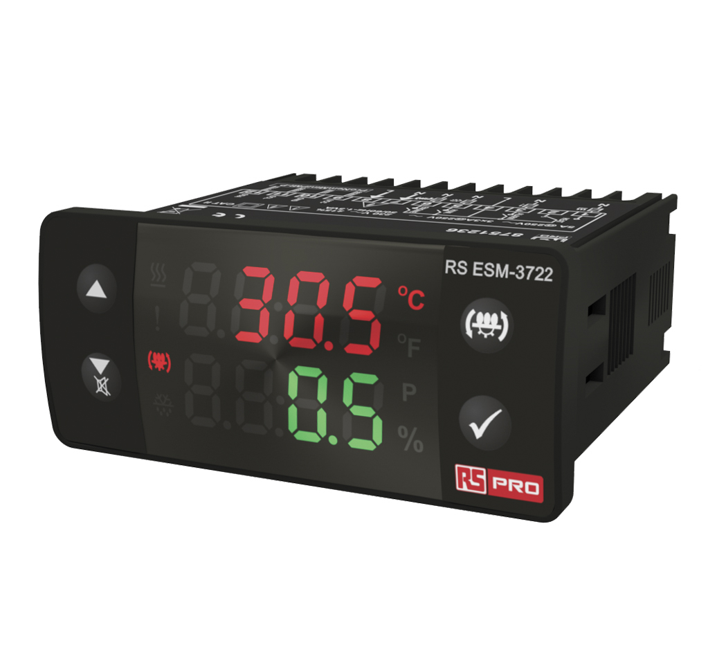
In some applications, a dual-color display can also be a desirable feature, making it easy to identify different controller states. Some products also have displays that can change from red to green or vice versa depending on preprogrammed conditions, such as indicating an alarm condition. In this case, no alarm might be shown by a green display, but if an alarm is present the display would turn red.
Types of Controllers
Temperature controllers come in many different styles with a vast array of features and capabilities. There are also plenty of ways to categorize controllers according to their functional capabilities. In general, temperature controllers are either single loop or multi-loop. Single loop controllers have one input and one or more outputs to control a thermal system. On the other hand, multi-loop controllers have multiple inputs and outputs, and are capable of controlling several loops in a process. More control loops permit controlling more process system functions.
Reliable single loop controllers range from basic devices that require single manual setpoint changes to sophisticated profilers that can automatically execute up to eight setpoint changes over a given time period.
Analog

The simplest, most basic controller type is the analog controller. Analog controllers are low cost, simple controllers that are versatile enough for rugged, reliable process control in harsh industrial environments including those with significant electrical noise. Controller display is typically a knob dial.
Basic analog controllers are used mostly in non-critical or unsophisticated thermal systems to provide simple ON-OFF temperature control for direct or reverse acting applications. Basic controllers accept thermocouple or RTD inputs and offer optional percent power control mode for systems without temperature sensors. Their basic drawback is a lack of readable display and lack of sophistication for more challenging control tasks. Plus, the absence of any communication ability limits their use to simple applications such as ON/OFF switching of heating elements or cooling devices.
Limit
These controllers provide safety limit control over process temperature. They have no ability to control temperature on their own. Put simply, limit controllers are independent safety devices to be used alongside an existing control loop. They are capable of accepting thermocouple, RTD, or process inputs with limits set for high or low temperature just like a regular controller. Limit control is latching and part of redundant control circuitry to positively shut a thermal system down in case of an over-limit condition. The latching limit output must be reset by an operator; it will not reset by itself once the limit condition does not exist. A typical example would be a safety shut off for a furnace. If the furnace exceeds some set temperature, the limit device would shut the system down. This is to prevent damage to the furnace and possibly any product that may be damaged by excessive temperatures.
General Purpose Temperature Controllers

General-purpose temperature controllers are used to control most typical processes in industry. Typically, they come in a range of DIN sizes, have multiple outputs, and programmable output functions. These controllers can also perform PID control for excellent general control situations. They are traditionally placed in the front panel with the display for easy operator accessibility.
Most modern digital temperature controllers can automatically calculate PID parameters for optimum thermal system performance using their built in auto-tuning algorithms. These controllers have a pre-tune function to initially calculate the PID parameters for a process, and a continuous tune function to constantly refine the PID parameters. This allows for quick setup, saving time and reducing waste.
Valve Motor Drive
A special type of general-purpose controller is the valve motor drive (VMD) controller. These controllers are specifically designed to control valve motors used in manufacturing applications such as gas burner control on a production line. Special tuning algorithms give accurate control and fast output reaction without the need for slidewire feedback or excessive knowledge of three-term PID tuning algorithms. VMD controllers control the position of the valve, somewhere between 0% to 100% open, depending on the energy needs of the process at any given time.
Profile
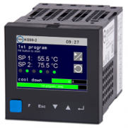
Profiling controllers, also called ramp-soak controllers, allow operators to program a number of setpoints and the time to sit at each setpoint. Programming a setpoint change is called ramp and the time to stay at each setpoint is called soak or dwell. One ramp or one soak is considered to be one segment. A profiler offers the ability to enter a number of segments to allow complex temperature profiles. The profiles can be referred to as recipes by the operator. Most profilers allow storage of multiple recipes for later use. Smaller profilers may allow for four recipes with sixteen segments each with more advanced profilers allowing for more recipes and segments.
Profile controllers are able to execute ramp-and-soak profiles such as temperature changes over time, along with hold and soak/cycle duration, all the while being unattended by an operator.
Typical applications for profile controllers include heat treating, annealing, environmental chambers, and complex process furnaces.
Multi-Loop
Besides single-loop controllers which can control only one process loop, multi-loop controllers can control more than one loop, meaning they can accept more than one input variable.
Generally speaking, a multi-loop controller can be thought of as a device with many individual temperature controllers inside a single chassis. These are typically mounted behind the panel as opposed to in front of the panel as with general-purpose single loop controllers. Programming any one of the loops is similar to programming a panel-mounted temperature controller. However, multi-loop systems tend not to have the traditional, physical user interface (no display or switches), instead using a dedicated communications link.
Multi-loop controllers need to be configured by a specialized software program on a PC that can download the configuration to the controller using the dedicated communications interface.
Information can be retrieved via a communications interface. Common communications interfaces that are supported include DeviceNet, Profibus, MODBUS/RTU, CanOPEN, Ethernet/IP, and MODBUS/TCP.
Multi-loop controllers provide a compact modular system that can operate either within a stand-alone system or in a PLC environment. As a replacement for temperature controls in PLCs, they provide fast PID control and off-load much of the math intensive work from the PLC processor, allowing for faster PLC scan rates. As a replacement for multiple DIN controllers, they provide a single point of software access to all control loops. The cost of installation is reduced by eliminating much wiring, panel cutouts, and saving panel space.
Multi-loop controllers provide some additional features not available on traditional panel mounted controllers. For instance, multi-loop controllers have higher loop density for a given space. Some multi-loop temperature control systems can have up to 32 loops of control in a DIN rail mounted package not much longer than 8". They also reduce wiring by having a common connection point for power supply and communications interfaces.
Multi-loop temperature controllers also have enhanced security features, one of which is the absence of buttons where anyone can change critical settings. By having complete control over the information being read from or written to the controller, the machine builder can limit the information that any given operator can read or change, preventing undesirable conditions from occurring, such as setting a setpoint too high to a range that may damage product or the machine. In addition, controller modules can be hot-swapped. This lets a controller module be changed out without having to power down the system. Modules can also auto-configure after a hot swap.
Other Temperature Controller Characteristics
Supply Voltage
There are typically two supply voltage options when it comes to temperature controllers: low voltage (24VAC/DC) and high voltage (110-230VAC).
Size
Controllers come in several standard sizes that are referred to by DIN numbers such as 1/4 DIN, 1/8 DIN, 1/16 DIN and 1/32 DIN. DIN is an acronym for the roughly translated "Deutsche Institut fur Normung," a German standards and measurements organization. For our purposes, DIN simply indicates that a device complies with a generally accepted standard for panel dimensions.

| DIN Size | 1/4 | 1/8 | 1/16 | 1/32 |
|---|---|---|---|---|
| Size in mm | 92 x 92 | 92 x 45 | 45 x 45 | 49 x 25 |
| Size in inches | 3.62 x 3.62 | 3.62 x 1.77 | 1.77 x 1.77 | 1.93 x 0.98 |
The smallest size is the 1/32 DIN, which is 24mm × 48mm, with a corresponding panel cutout of 22.5mm × 45mm. The next size up is the 1/16 DIN which measures 48mm × 48mm with a panel cutout size of 45mm × 45mm. The 1/8 DIN is 48mm × 96mm with a 45mm × 92mm panel cutout. Lastly, the largest size is the 1/4 DIN measuring 96mm × 96mm with a 92mm × 92mm panel cutout.
It is important to note that the DIN standards do not determine how deep a controller may be behind a panel. The standards only allow for front panel dimensions and panel cut-out dimensions.
Agency Approvals
It is desirable for a temperature controller to have some sort of agency approval to ensure that the controller meets a minimum set of safety standards. The type of approval depends on the country in which the controller will be used. The most common approval, UL and cUL registration, applies to all controllers used in the U.S. and Canada. Usually, there is one certification required for each country.
For controllers that are used in European Union countries, CE approval is necessary.
A third type of approval is FM. This applies only to limit devices and for controllers in the U.S. and Canada.
Front Panel Enclosure Rating
An important controller characteristic is the front panel enclosure rating. These ratings can be in the form of an IP rating or a NEMA rating. IP (Ingress Protection) ratings apply to all controllers and are usually IP65 or higher. This means that from the front panel only, the controller is completely protected from dust and against low pressure jets of water from all directions with only limited ingress permitted. IP ratings are used in the U.S., Canada, and Europe.
A controller's NEMA (National Electrical Manufacturers Association) rating is parallel to the IP rating. Most controllers have a NEMA 4 or 4X rating, which means they can be used in applications requiring water washdown only (not oils or solvents). The ‘X' in a NEMA 4X rating means that the front panel won't corrode. NEMA ratings are used primarily in the U.S. and Canada.
===========================================================
What is a PID Controller?
A PID controller is a device containing a control loop mechanism. These instruments can be used in industrial control applications to regulate a range of process variables including temperature, pressure and speed.
PID (Proportional Integral Derivative) controllers work by forcing feedback to match a desired setpoint through the use of a mathematical formula calculating the differential between the setpoint and the current state of the variable being monitored. The device then uses the results of this calculation to automatically compensate for detected changes in the system as needed, ensuring that the process variable remains as close to the required setpoint as possible.

The History of the PID Controller
Very early attempts at this continuous control of systems under load were seen as far back as the 1600s. One of the earliest examples was invented in the 17th-century when a centrifugal governor mechanism (based on rotating weights) was designed to compensate for increasing differential in rotation speeds between larger and smaller millstone wheels under higher loads.
In 1922, Nicolas Minorsky made a real breakthrough towards what we now recognise as true PID control. Minorsky's observations and mathematical treatment would eventually evolve to give us the electronic industrial control mechanisms widely used as PID systems today.
PID controllers are now used widely in many industrial processes and they have become some of the most common items of automation and control gear used across multiple sectors and industries. This is largely due to the fact that PID controllers are ideally suited to delivering dependable, robust performance across a broad spectrum of environments and applications. They are also inherently user-friendly and simple in terms of both design and operation.
What are the Different Types of Temperature Control Devices?
In order to learn more about PID temperature controllers, it’s helpful to understand how other types of temperature control devices function in order to highlight the key differences.
In the simplest terms, all temperature control devices effectively work in a similar way. Their core role is to monitor and calculate, via an ongoing series of measurements from a sensor such as a thermocouple, the precise difference between the operator’s desired process temperature (the setpoint) and the current process temperature at any given time.
To be able to perform automatic temperature adjustments, all control devices will require a form of controller module which allows them to calculate an appropriate response function based on the readout from the sensor. The resulting instruction is then output to the control element. This could be a heater, fans, a closed-loop liquid cooling system, or a combination of all three.
The key fundamental differences between various types of temperature control devices lie within the precise method in which they use and react to this sampled information and the steps that they then take in order to exercise their respective versions of temperature control. As a result, there are three core temperature control device types, as seen below:
On-Off Temperature Controllers
The device performs a basic, binary switching function (it’s either on or off) in order to help adjust process temperatures in response to sensor input
These devices offer the simplest form of automated temperature control, and can only respond to the temperature crossing the setpoint one way or another
As such, they are generally only used in systems where absolute precision is not crucial, or where temperature changes only tend to occur very gradually
As the most basic form of automated temperature control, on/off devices often incorporate latching relay switches, which must be manually reset after they reach a specified shutoff temperature
One problem that this type of temperature control can struggle with is rapid cycling between off/on states, triggered by the sensor registering borderline results as the temperature hovers very close to the setpoint
To combat this, they can be engineered to include hysteresis, which in practice means that there is a built-in buffer zone to prevent the device chattering between on/off within a range of safe temperatures

Proportional Temperature Controllers
A proportional temperature control device takes a more sophisticated approach than simply relying on hysteresis to prevent device chatter between on/off states
Instead, it is able to increase or throttle back power as required, in a ratio that matches the differential between the current process temperature and the setpoint
For better efficiency and economy, this proportional control usually takes place only within a defined range of temperatures at either side of the setpoint
Outside of this relatively narrow window, the device returns to a binary on/off operating model
An inherent limitation of proportional controllers is that because they reduce their adjustment curve as the temperature approaches the setpoint, a precise zero differential is never actually reached

PID Temperature Controllers
PID controllers take the proportional model one step further by incorporating proportional control alongside two other algorithms for adjustment, namely integral and derivative measurements
In simple terms, the integral is the sum of all measurements taken over a specified time period. It works like an error average and helps to compensate for the drop-offs in proportional control
The derivative is effectively the measured rate of temperature change and helps to fine-tune the integral to prevent overshoot
PID temperature controllers can, therefore, offer a much more sensitive, versatile and reactive approach in reading and adjusting to measurements
They are best used in systems where pinpoint accuracy is critical, or where low overall mass/volume in the system makes it more likely that problematic fluctuations will occur suddenly and frequently

What are the Advantages of a PID Temperature Controller?
The key advantage of a PID temperature controller over standard thermistors, thermocouples and other temperature-monitoring/heating devices is that PID controllers are extremely effective at reacting to sudden disturbances and fluctuations in ongoing processes. These can have a dramatic impact on the quality of the product being measured or produced if left unchecked for any length of time, which is where a PID temperature controller comes in especially handy. These devices excel at dealing with such disturbances almost instantaneously.
Applications of PID Controllers
PID controllers are widely used in all manner of industries, sectors and applications.
In addition to being relatively easy to set and adjust, the accuracy of their control loop feedback mechanisms makes PID instruments highly effective at digitally tracking - and automatically regulating - various processes and environmental factors across a wide range of variables.
In fact, while this guide is specifically concerned with PID temperature controllers, the basic function of a PID device can be applied to a much broader spectrum of automation and control processes including flow rate, pressure, speed, frequency and more.
Temperature Control
As previously mentioned, the PID temperature controller shares certain characteristics with other types of temperature control device. In particular, it still takes its readings from a sensor (often a thermocouple or similar), and typically outputs instructions via a digital control component to a mechanical actuator device such as a heater or fan array.
The highly universal nature of this basic monitoring and adjustment model means that PID controllers have a broad spectrum of potential temperature control applications in many industries, including:
Furnace and batch temperature control
Curing and conditioning of various sheet materials
Temperature-critical drying and evaporation processes
Heat treatment and tempering of industrial parts and equipment
Medical sciences and pharmaceutical development
Food production and preparation
PID Controller Tuning
PID devices are typically shipped by their manufacturers with default settings programmed for the proportional, integral and derivative. Operators installing and using any type of PID instrument must first calibrate the device, making sure it is properly programmed and adjusted to suit the specific needs of the industrial process in question. This also includes ensuring that the environmental parameters that it is required to operate between are appropriate for the potential variables occurring within that process. Until this process has been completed, the PID controller cannot be left to automatically handle its assigned workload.
This is equally true for PID temperature controllers, and there are a number of different ways in which this tuning can be achieved. In practice, all the different methods aim for the same result, which is to adjust, or tune, each of the proportional, integral and derivative terms individually in order for the module as a whole to deliver the desired performance.
Simple trial and error is often viewed as the most practical method of tuning PID controllers for many systems and scenarios. It is based on installing the device in a working system and effectively zeroing out all the settings. The operator then begins with proportional value, adjusting the gain upward until it reaches a point where it is oscillating around the setpoint.
Once this state is reached - which would be unsatisfactory in an accuracy-critical system and exposes one of the key limitations of proportional-only temperature control devices - the values for integral and derivative can be adjusted respectively. The former, if done correctly, should start to limit the oscillation rate down to almost zero, whereas the latter will increase response speed as optimum settings for the system and device type installed are neared.
An alternative to trial and error is the Ziegler-Nichols method. This approach involves observation of both continuous cycling and damped oscillation under a closed-loop system. However, this method has certain limitations and many operators still prefer to use trial and error to achieve their desired results.
=========================================================